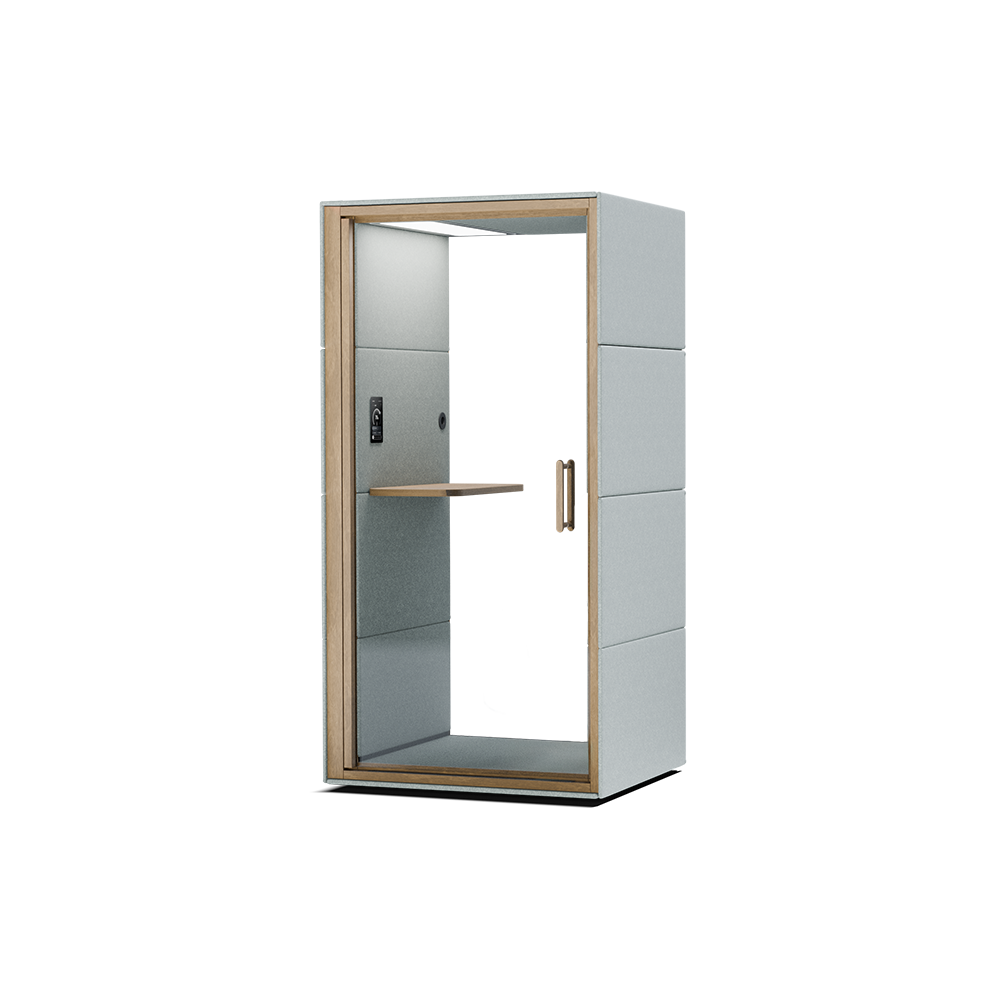
SPOT is a premium acoustic pod designed for quick calls and peak productivity. Tailored for individual use, it seamlessly merges functionality with aesthetics, creating a tranquil environment for focused work.
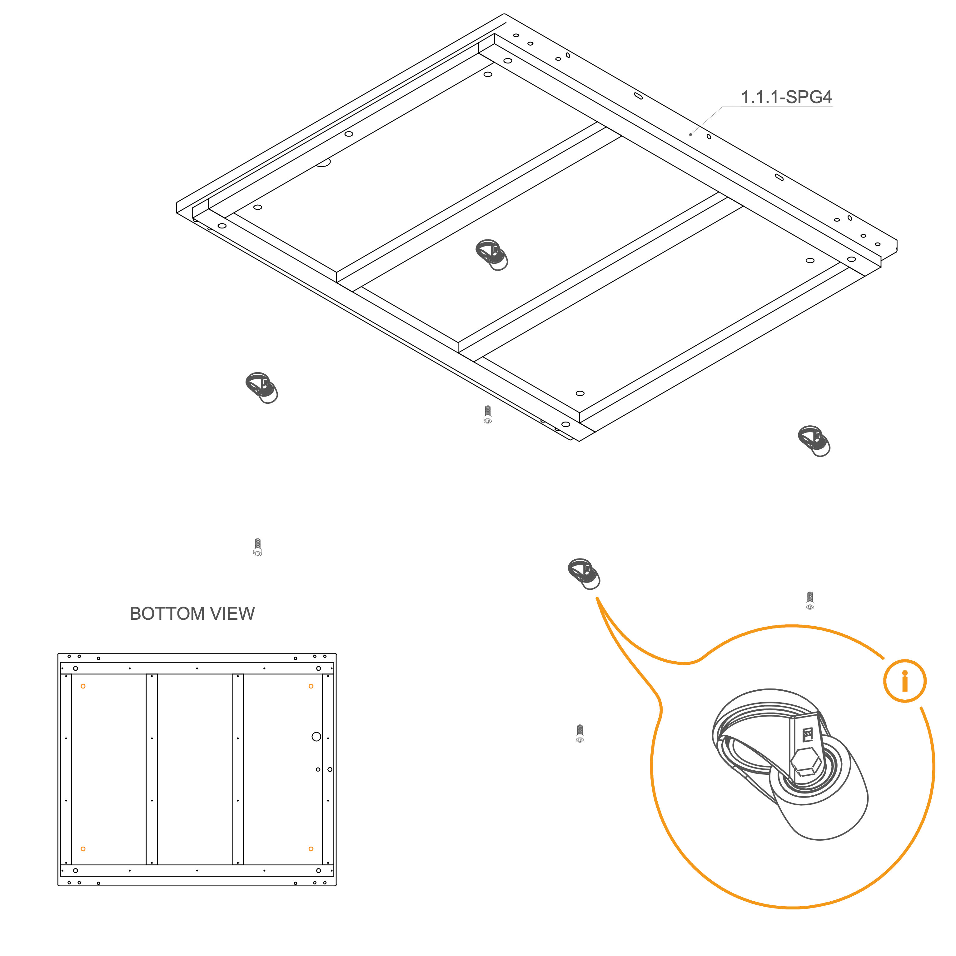
Use the marked holes in the picture to insert M10×25 mm screws (T0509). If your order includes wheels (V0181), attach them to the same holes using the M10×25 mm screws (T0509).
Parts used:
wheel | V0181 | 4×
M10×25 mm screw | T0509 | 4×
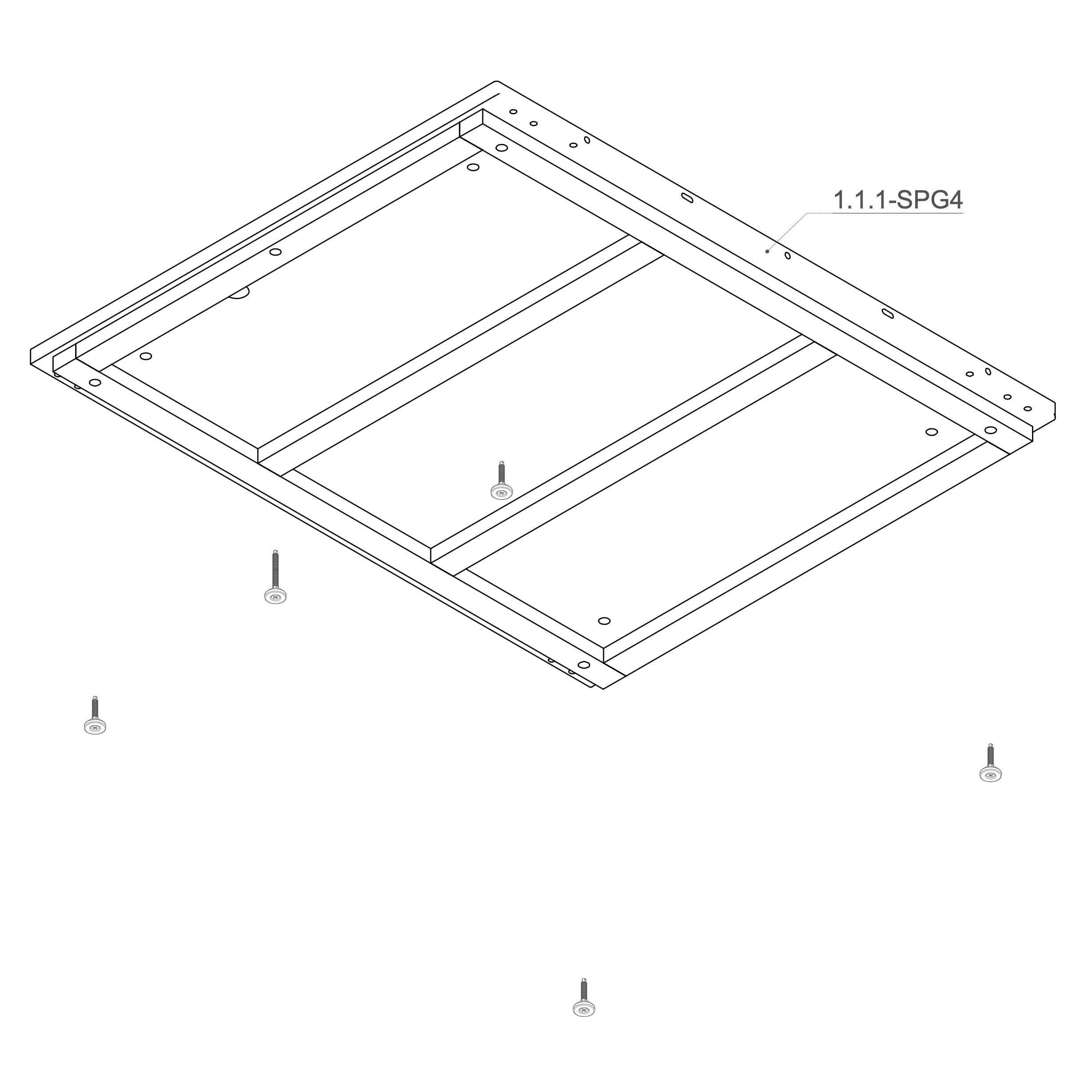
2. Install Leveling Feet
Keep the 1.1.1-SPG4 floor panel flipped upside down (bottom side up).
Insert one levelling foot (V0050) into each of the 8 marked holes on the underside of the floor panels.
Using a Phillips head screwdriver, partially screw in the standing feet. Leave approximately 20 mm of clearance to allow for future adjustments—do not fully tighten them at this stage.
Parts used:
M10×55 mm adjustable foot | V0050 | 4×
M10×100 mm adjustable foot | V0176 | 1×
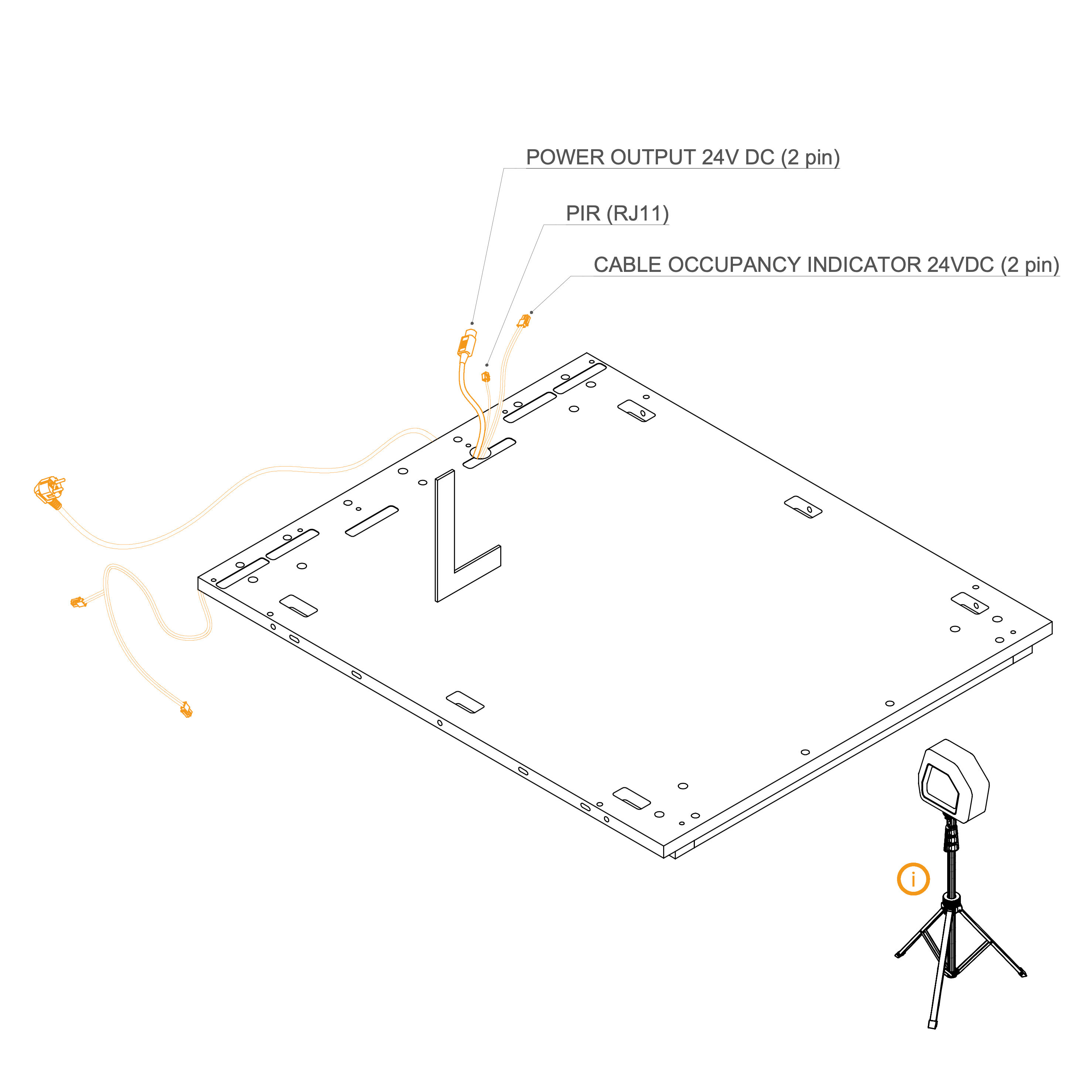
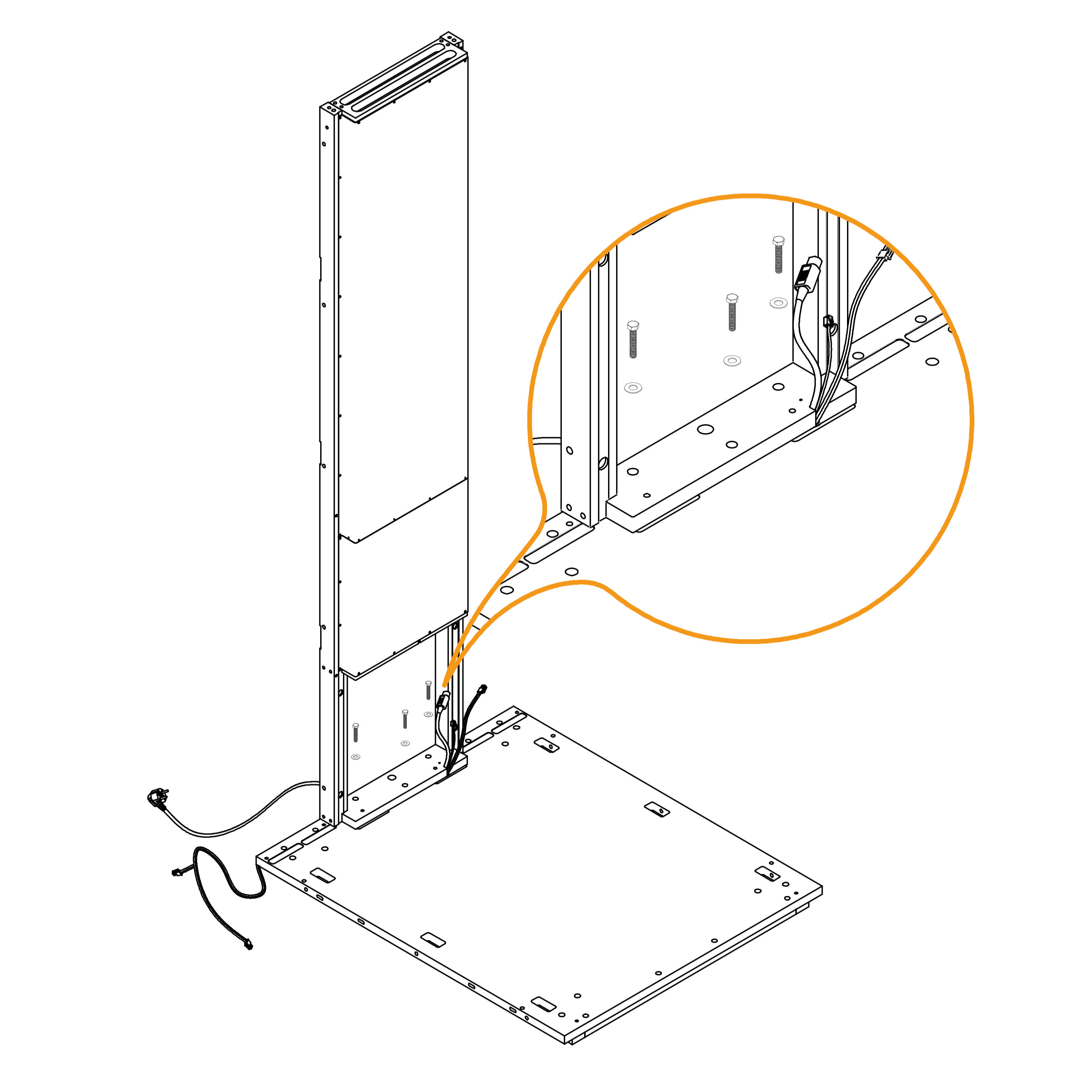
3. Route Cables Through the Hole
Lay the GEN4_ELEKTRO_CABLE OCCUPANCY SIGNALIZATION 4600 mm (E0816), LAN cable (RJ45), and power cord through the hole in the floor panel. Follow the marked path shown in the bottom view, ensuring the cables are not pinched.
Use a laser level and L-angle (or a spirit level) to level the floor. Adjust the height of the standing feet using a Philips head bit.
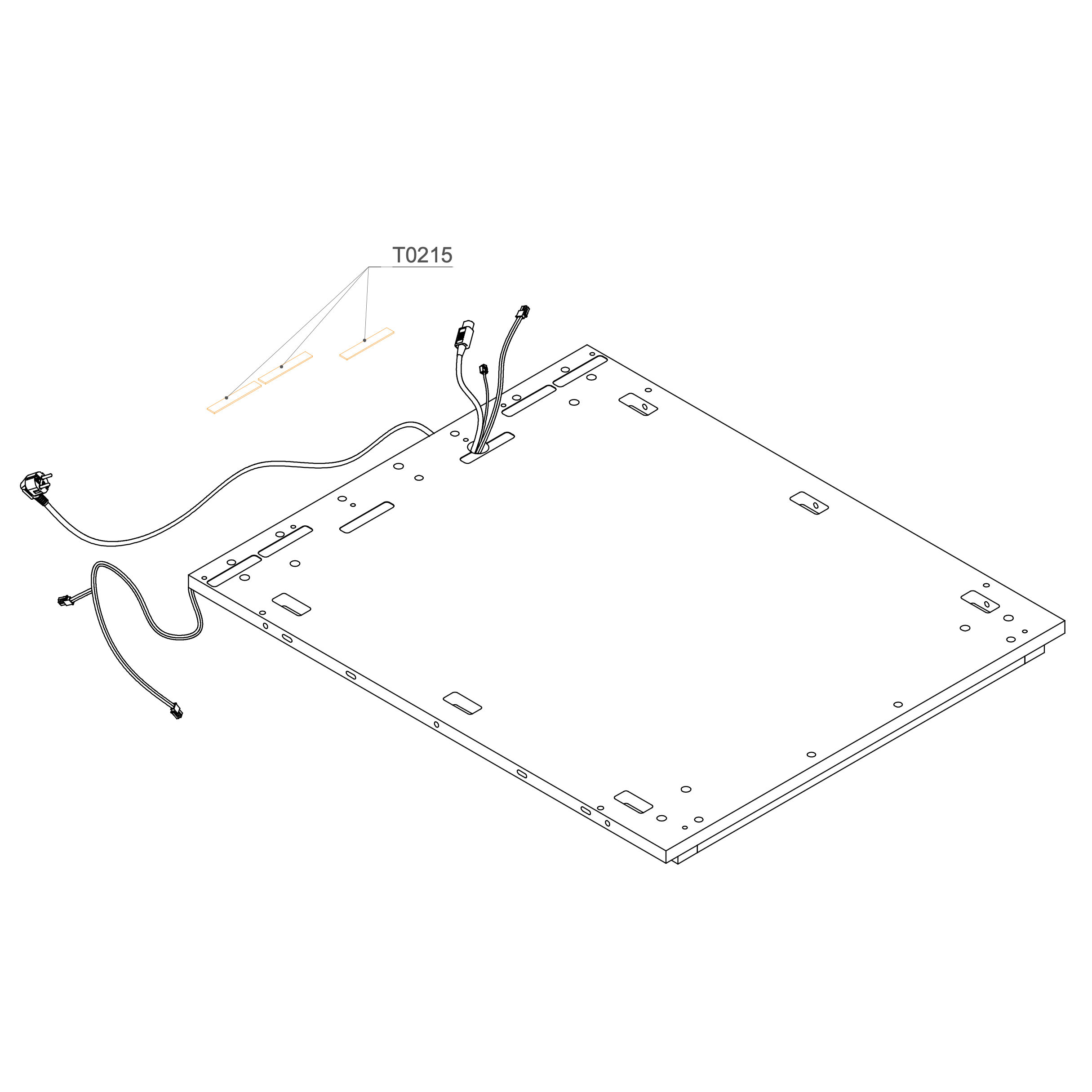
4. Insert Spacers
Insert the three spacers (T0215) into the cutouts located on the door side of the pod.
Parts used:
T0215 | Spacer | 3×
Dock
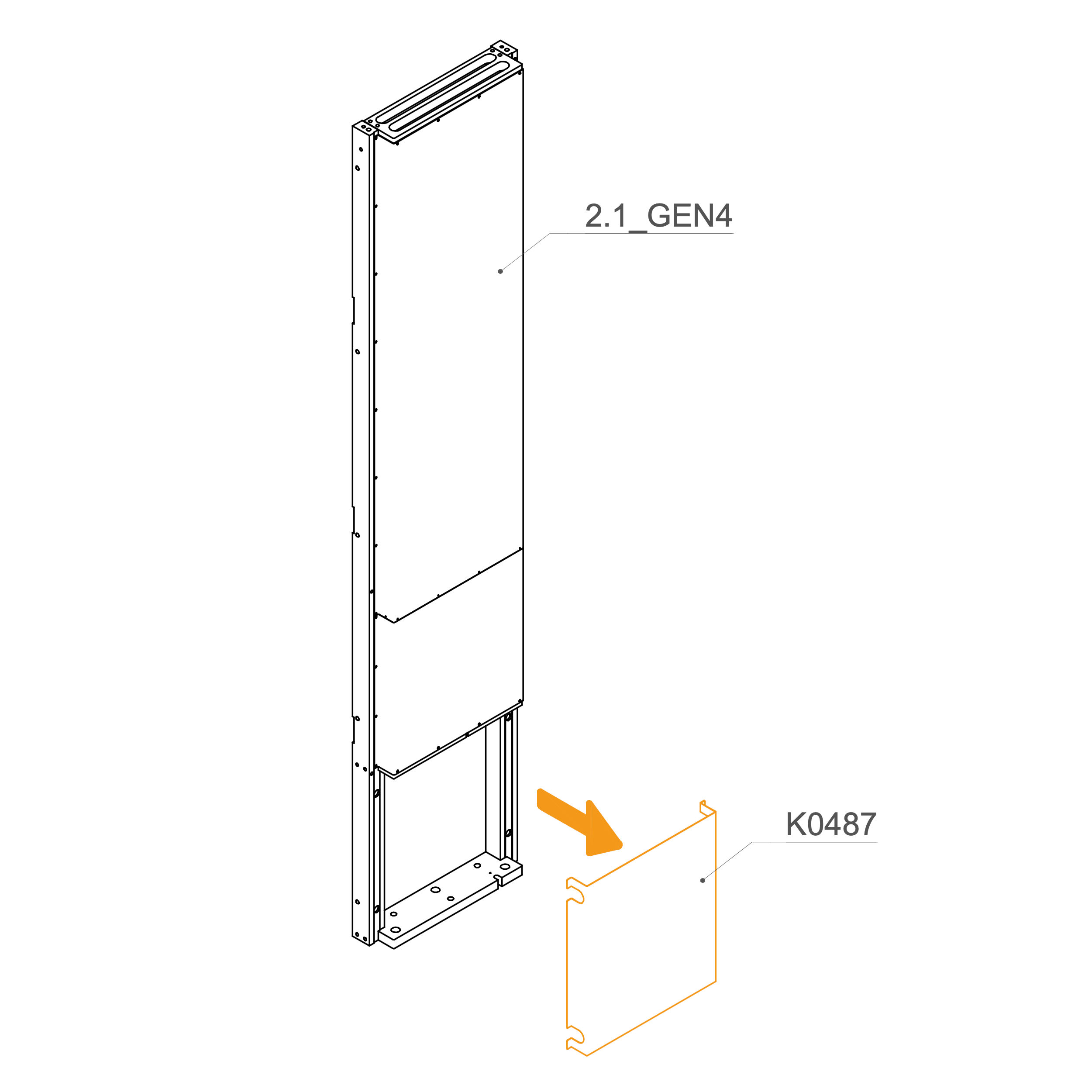
5. Remove Revision Doors
Remove the Revision Door (K0487) from the dock.
Parts used:
revision door K0487 | 1×
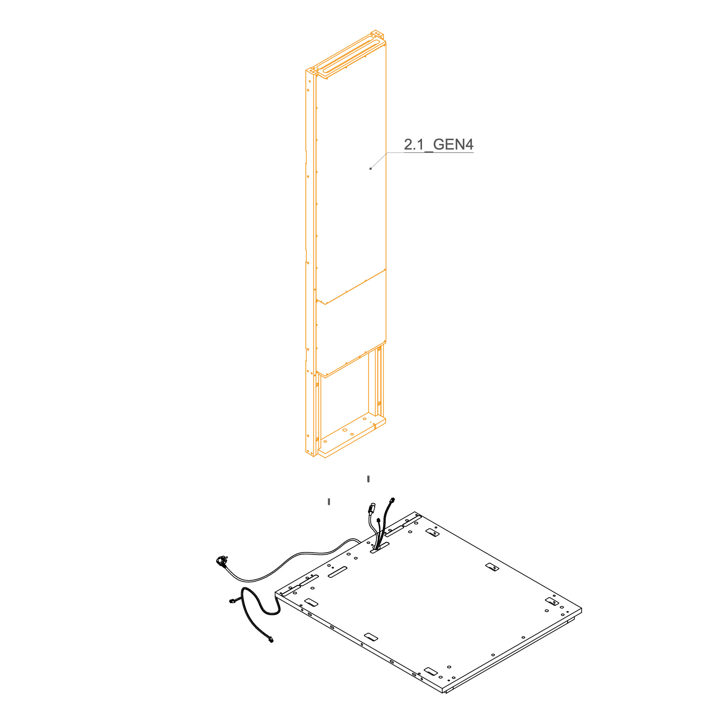
6. Position Dock Frame
Insert 8×30 mm dowel pins (T0122) into the predrilled holes on the floor panel to maintain proper alignment.
Position dock 2.1-GEN4 in place.
Parts used:
8×30 mm dowel pin | T0122 | 2×
7. Mount Dock on the Floor Panel
Insert M8×45 mm hex‑head bolts (T0204) through the inner mounting holes.
Place a washer (T0198) underneath each bolt head.
Pull the power cord, PIR sensor cable, and signalization cable through the opening in the dock panel for later connection.
Tighten securely until the bolt and washer are seated flush with the panel surface.
Parts used:
T0204 | M8×45 mm bolt | 3×
T0198 | Washer 8.4×24×2.0 mm | 3×
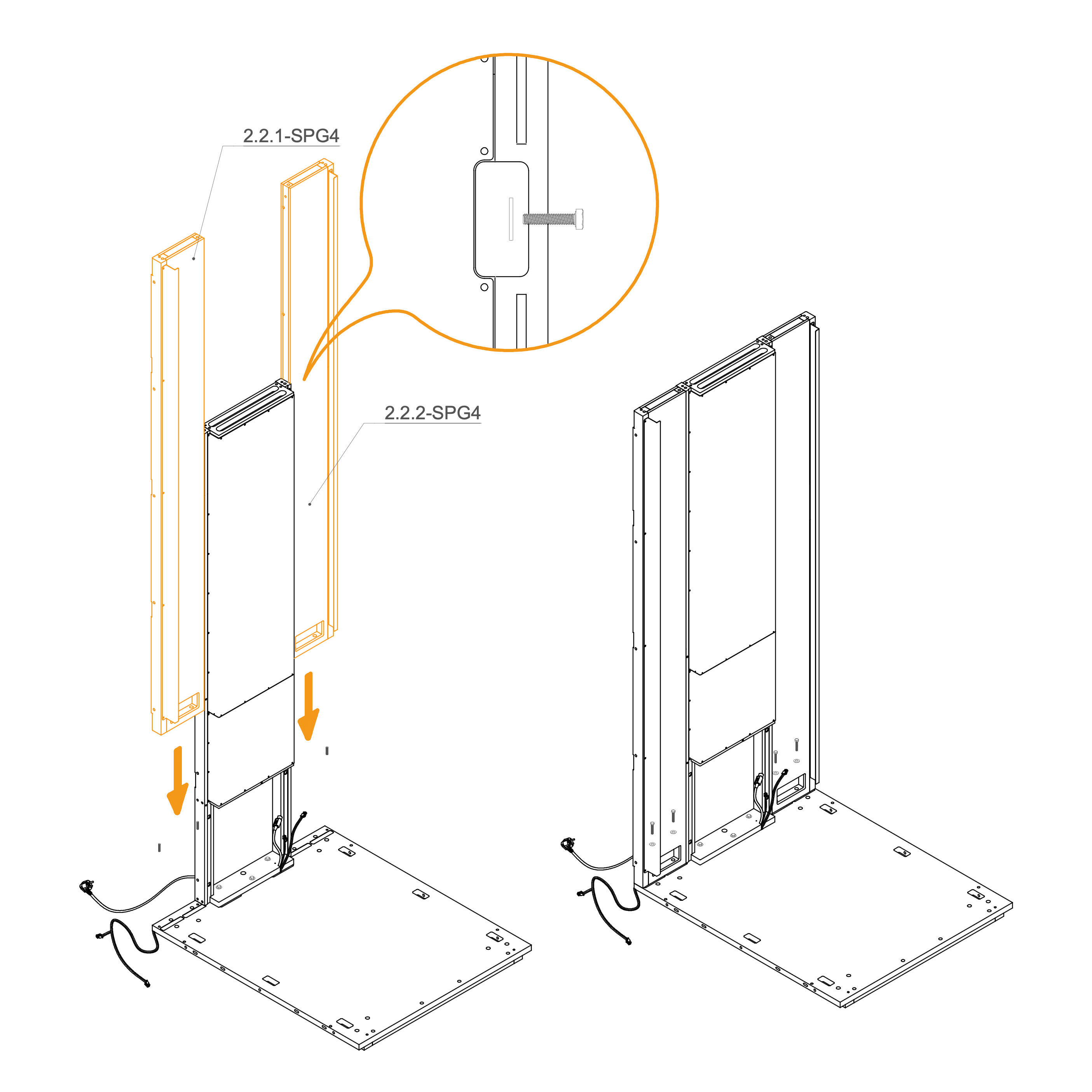
8. Attach Side Dock Panels
Insert dowels into the predrilled holes into the top of the docks and floor to maintain proper alignment.
Insert M8×45 mm hex‑head bolts (T0204) through the inner mounting holes.
Place a washer (T0198) underneath each bolt head.
Tighten securely until the bolt and washer are seated flush with the panel surface.
Use the cut-outs on the exterior side of the dock panels to draw them tightly together.
Insert an M6 × 30 mm bolt through the aligned holes. Place a washer under the bolt head and thread an M6 flange nut onto the bolt from the opposite side.
Parts used:
T0122 | 8×30 mm dowel | 4×
T0204 | M8×45 mm bolt | 4×
T0511 | M6×30 mm bolt | 5×
T0198 | Washer 8.4×24×2.0 mm | 9×
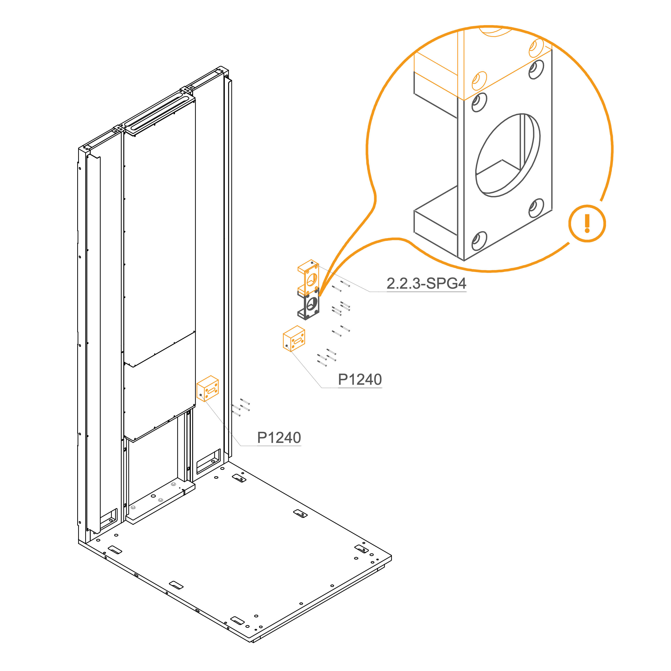
9. Install Wood Bracing
Anchor the wood bracing P1240 and 2.2.3-SPG4 for mounting the table and socket using screws. The second socket is optional.
Parts used:
M4×55 mm screw | T0270 | 12/16×
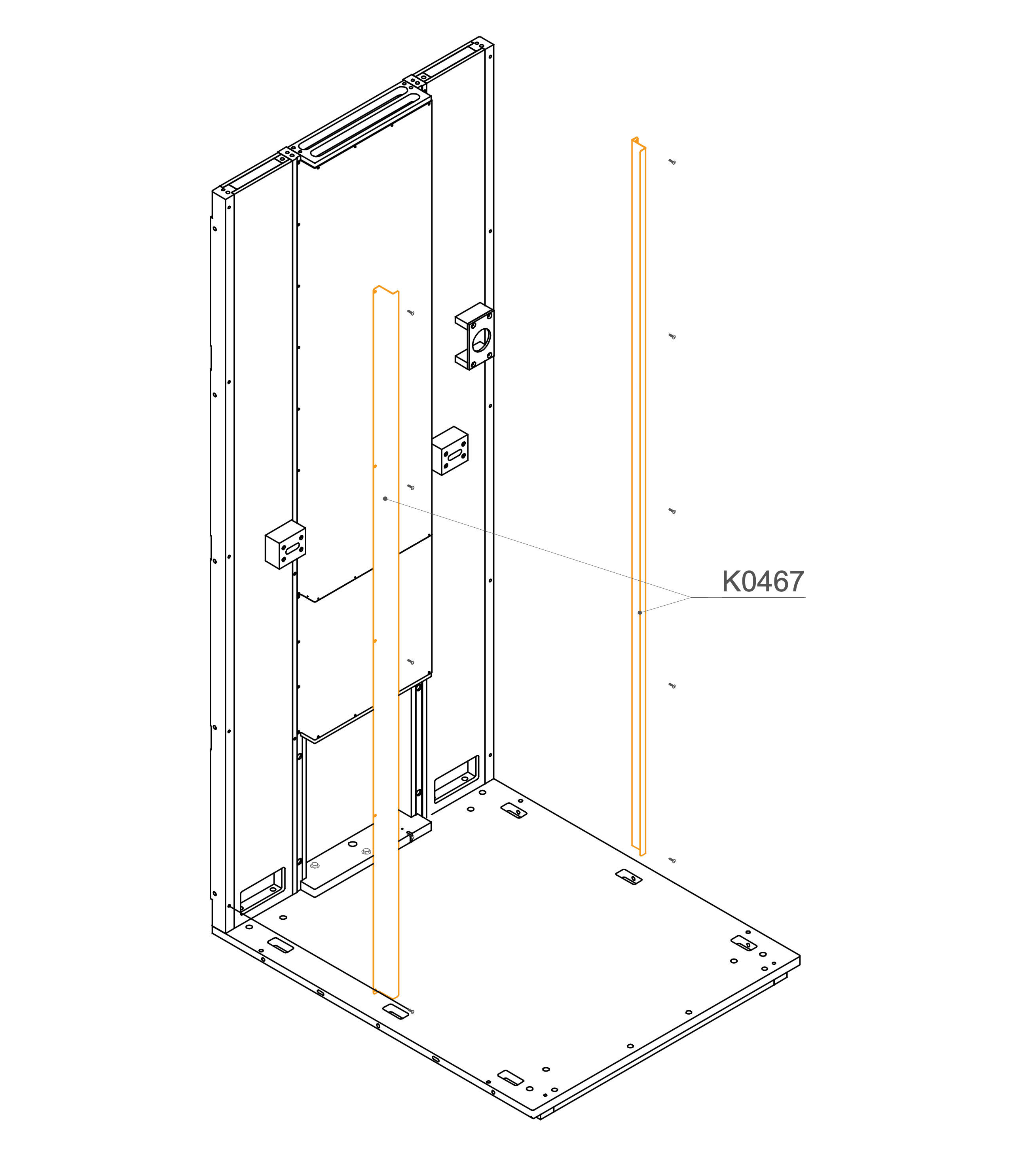
10. Secure the Dock to the Floor Panel
Anchor the metal profiles as shown.
Parts used:
M4×16 mm screw | T0308 | 10×
Rear Panel
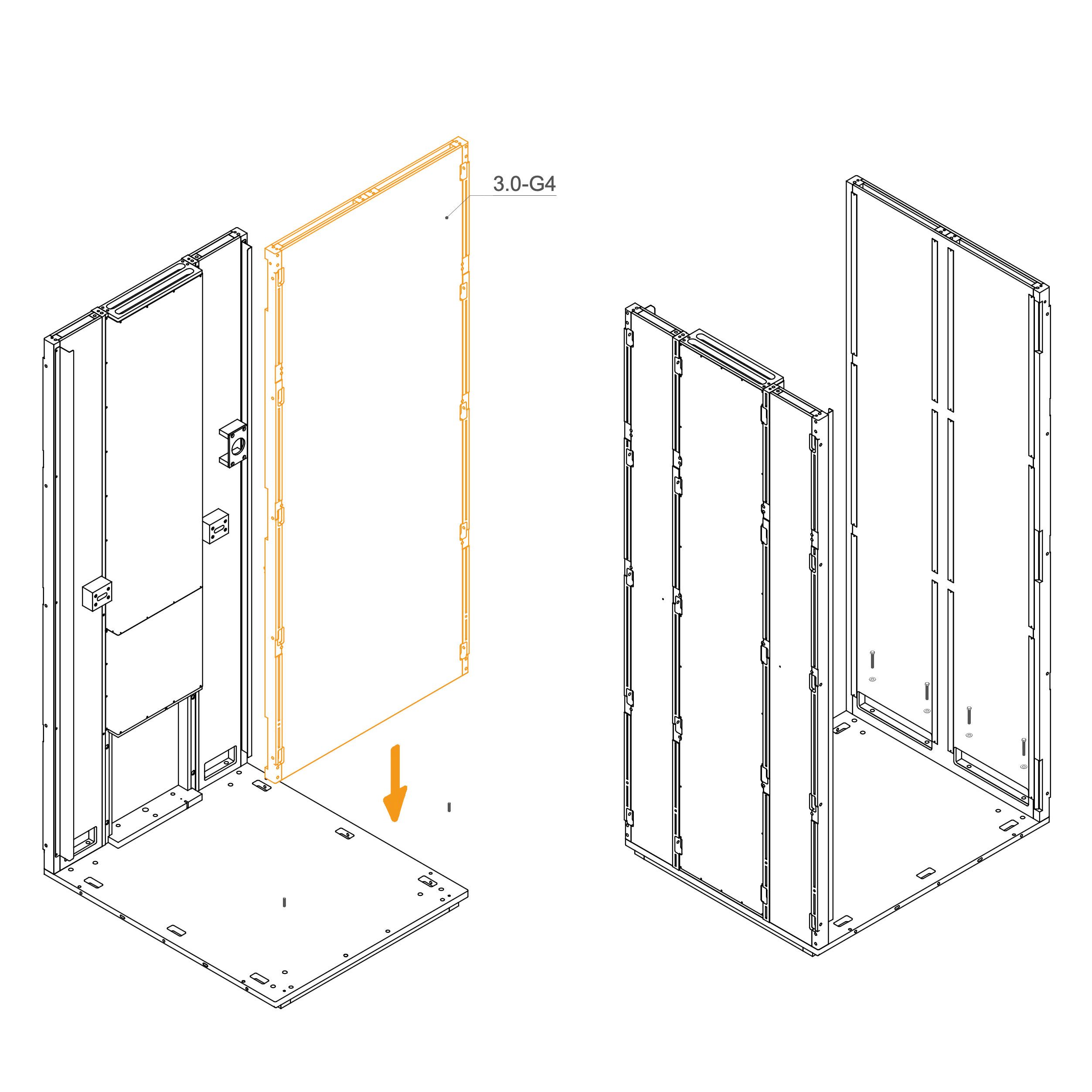
11. Mount Wall Panel to the Floor
Insert dowel pins (T0122) into the predrilled holes in the floor panel.
Align the panel with the floor panel.
Secure the bottom of the panel using M8×45 mm hex head bolts (T0204) and washers (T0198) through the mounting points.
Parts used:
8×30 mm dowel | T0122 | 2×
M8×45 mm bolt | T0204 | 4×
Washer 8.4×24×2.0 mm | T0198 | 4×
Roof
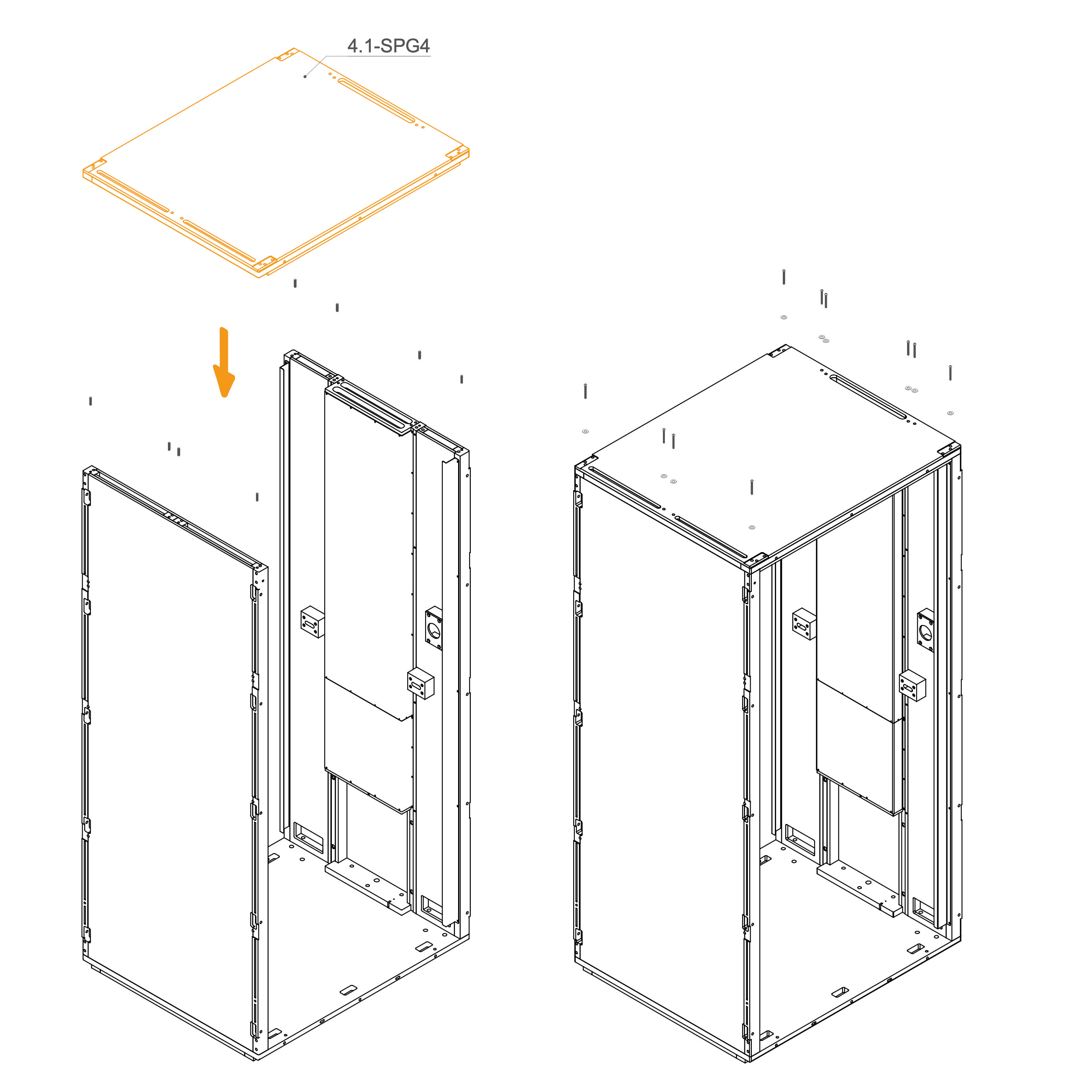
12. Attach Roof
Insert dowel pins (T0122) into the designated guide holes along the top edges of the wall panels.
Carefully lower the roof panel onto the structure, aligning the dowel pins with the corresponding holes on the underside of the roof.
Ensure the panel sits flush and is properly seated before proceeding to fasten.
Fasten the roof panel 4.1-SPG4 to the structure using M6×60 mm flat head bolts (T0510).
Place a washer (T0198) under each bolt head.
Tighten all bolts to securely attach the roof panel.
Parts used:
M8×30 mm dowel | T0122 | 8×
M6×60 mm bolt | T0510 | 8×
Washer 8.4×24×2.0 mm | T0198 | 8×
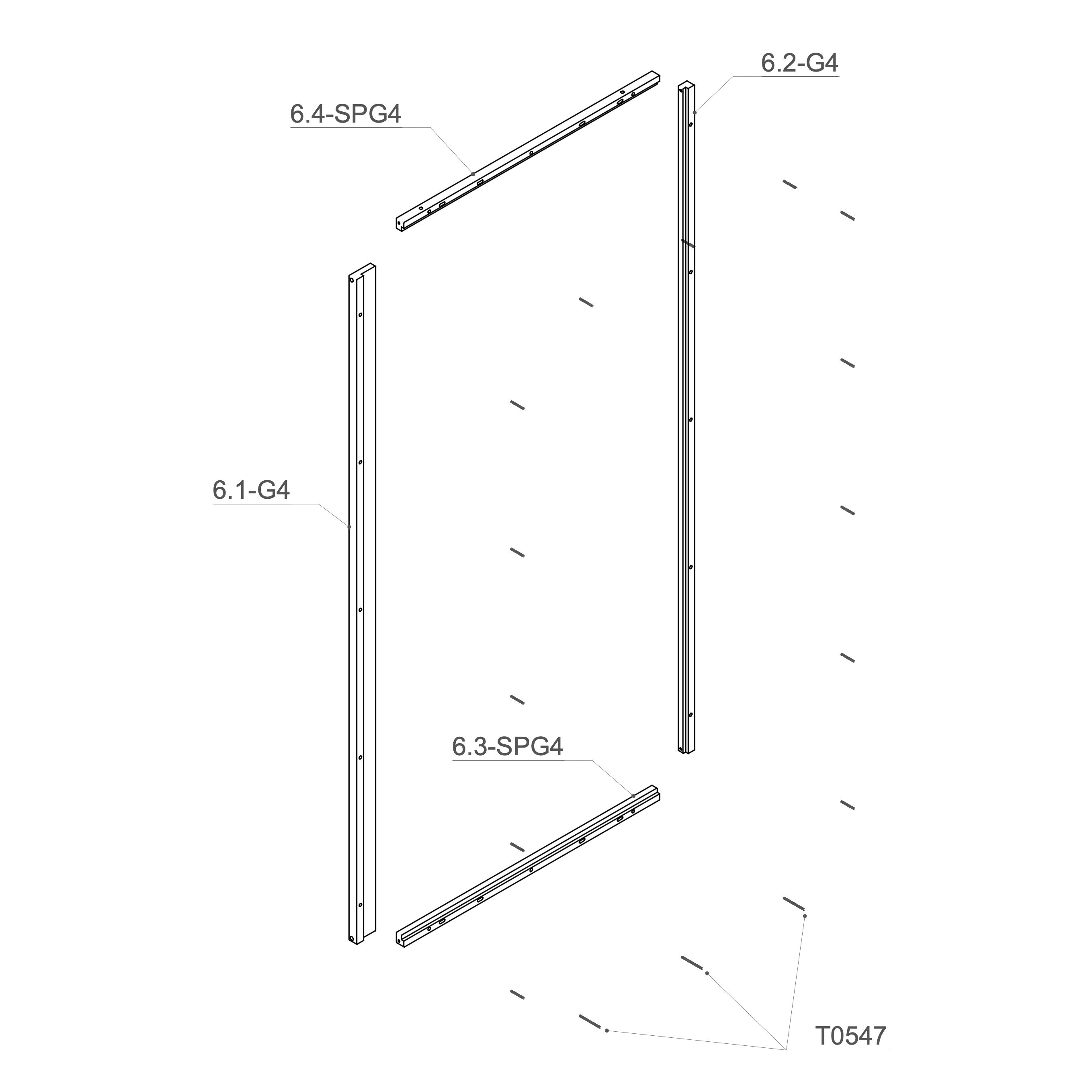
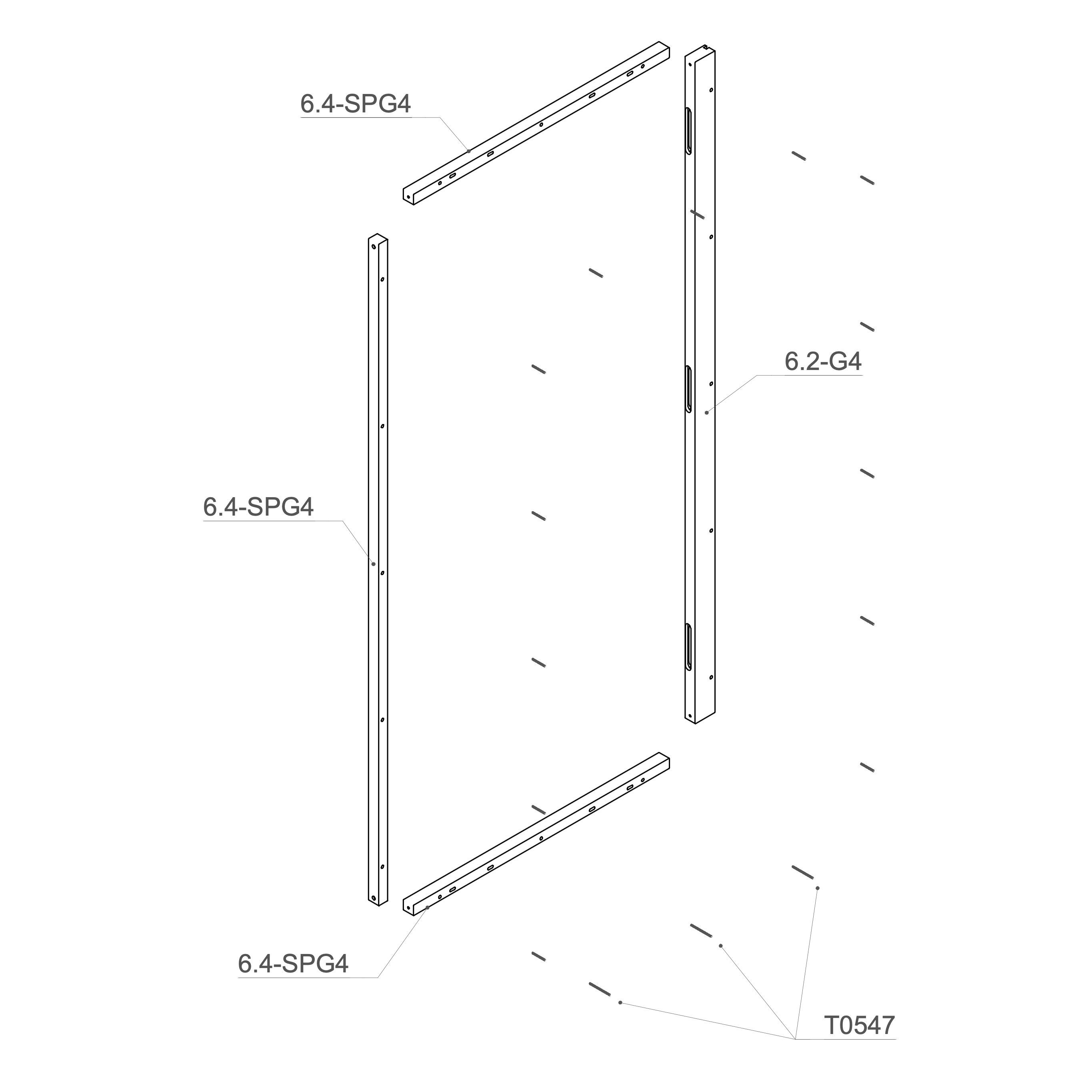
13. Attach Threaded Rod to Rear Frame
Place the M6×90 mm threaded rod (T0547) into the 6.3-SPG4 and M6×50 mm threaded rod (T0515) into the 6.1-G4, 6.2-G4 and 6.4-SPG4.
Parts used:
M6×50 mm bolt | T0515 | 13×
M6×90 mm bolt | T0547 | 3×
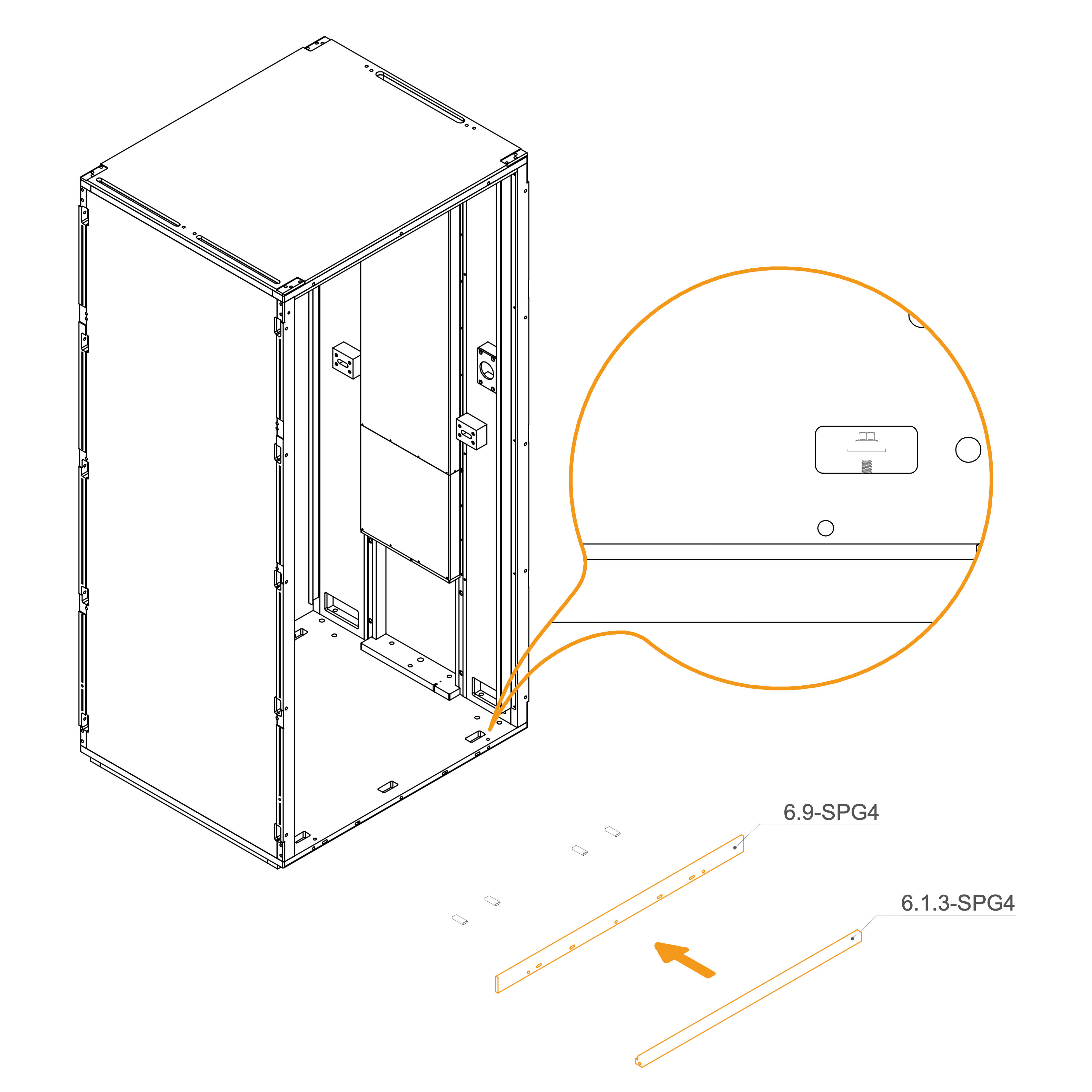
14. Attach Rear Frame to the Floor Panel
Insert D8×50×22 mm dowels (T0536) into the oval holes
Align the horizontal frame 6.9-SPG4 and 6.1.3-SPG4 with the mounting slots at the rear edge of the floor panel.
Place washers (T0198) and M6 flange nuts (T0514) on the threaded rod in the floor cutouts.
Ensure the frame is aligned correctly before tightening properly.
Parts used:
flange nut M6 | T0514 | 3×
washer | T0198 | 3×
dowel pin D8×50×22 mm | T0536 | 4×
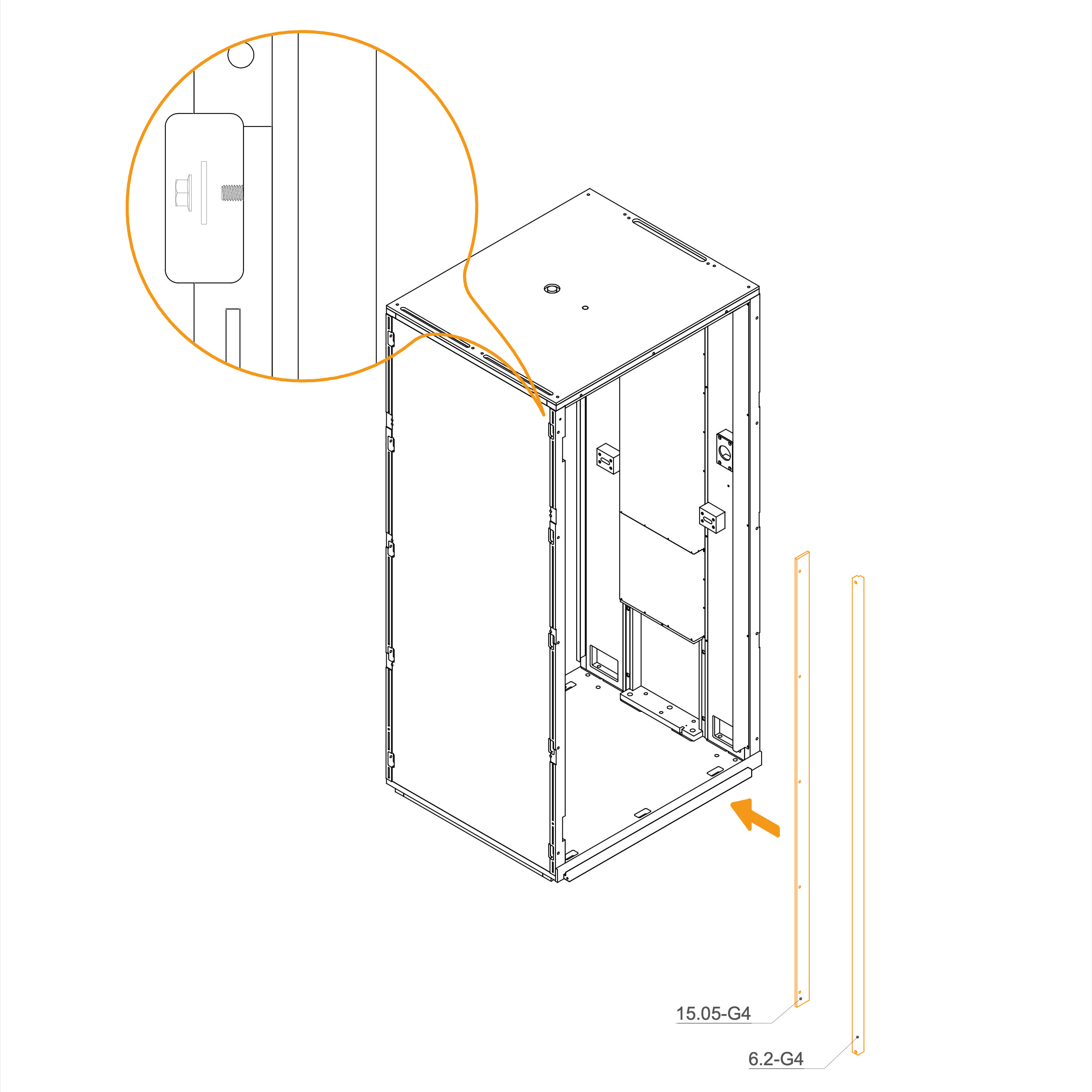
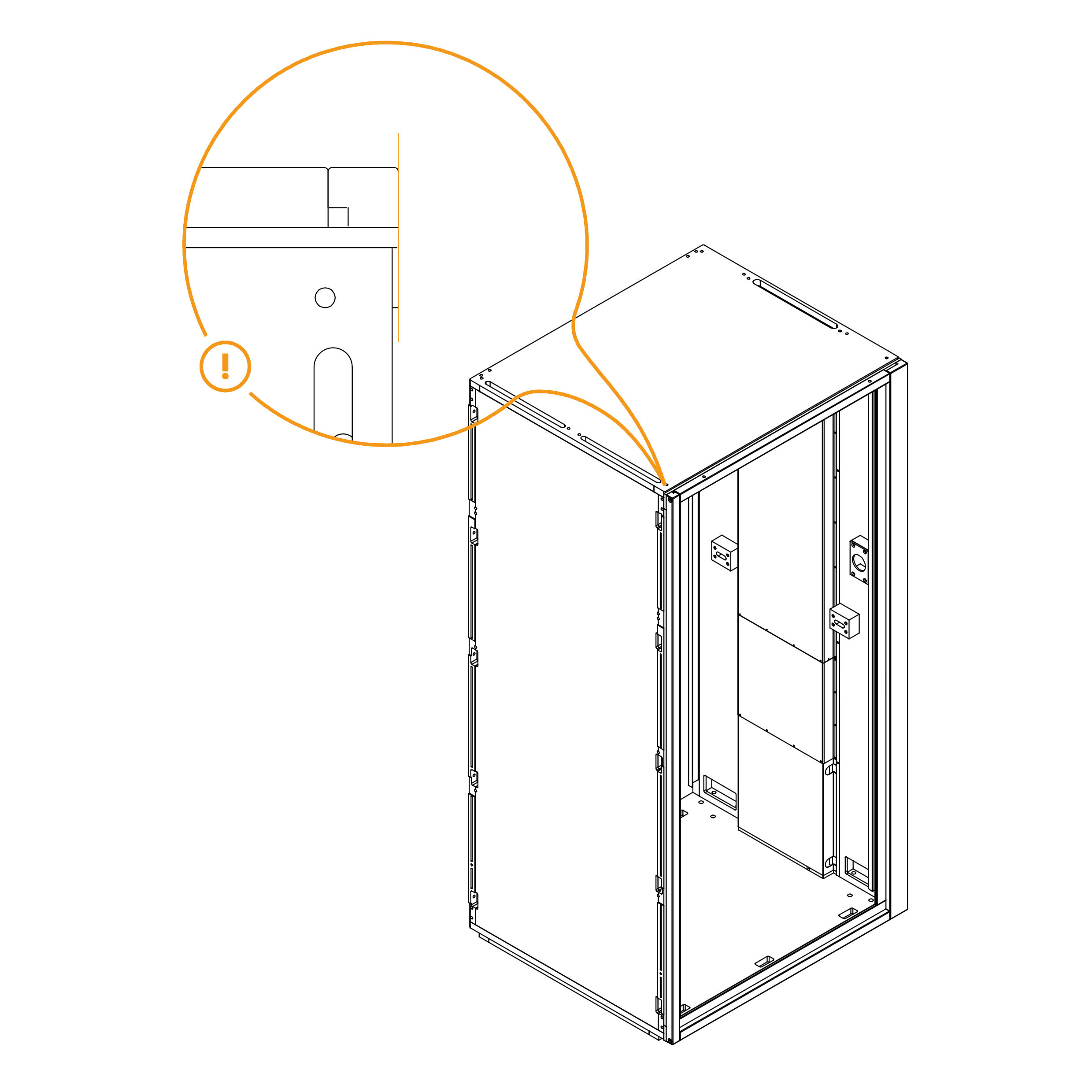
15. Attach Rear Frame to the Wall Panel
Place the two vertical frames, 6.2-G4 and 15.05-G4, in their designated positions.
Secure each frame by inserting a washer (T0198) and tightening an M6 flange nut (T0514) onto the threaded rod in the slot openings.
Ensure the frames are properly aligned before fully tightening the nuts.
Parts used:
washer 8.4×24×2.0 mm | T0198 | 5×
flange nut M6 | T0514 | 5×
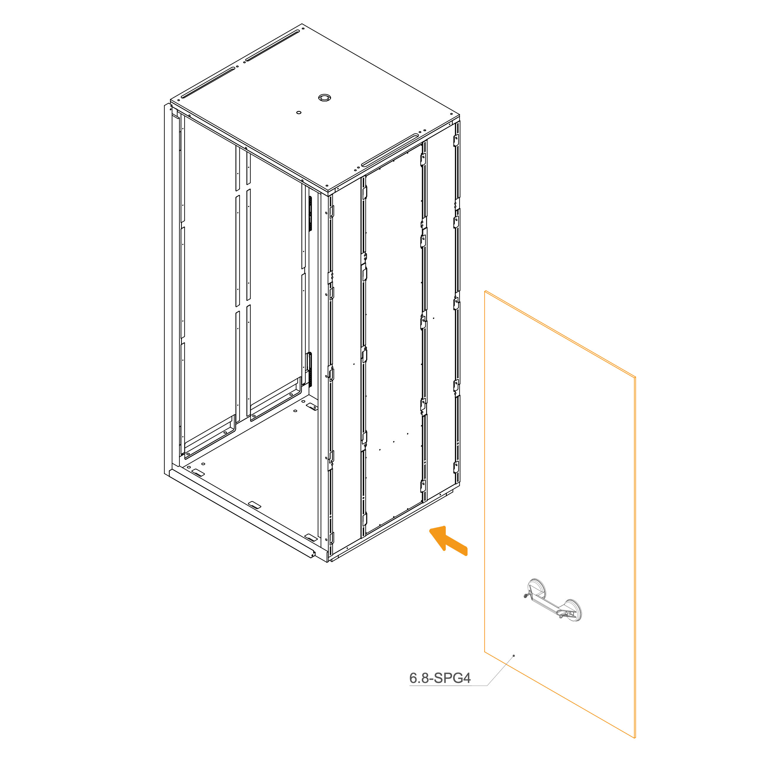
16. Install Rear Glass into the Frame
Insert the glasses 6.8-SPG4 into the groove in the Rear frame.
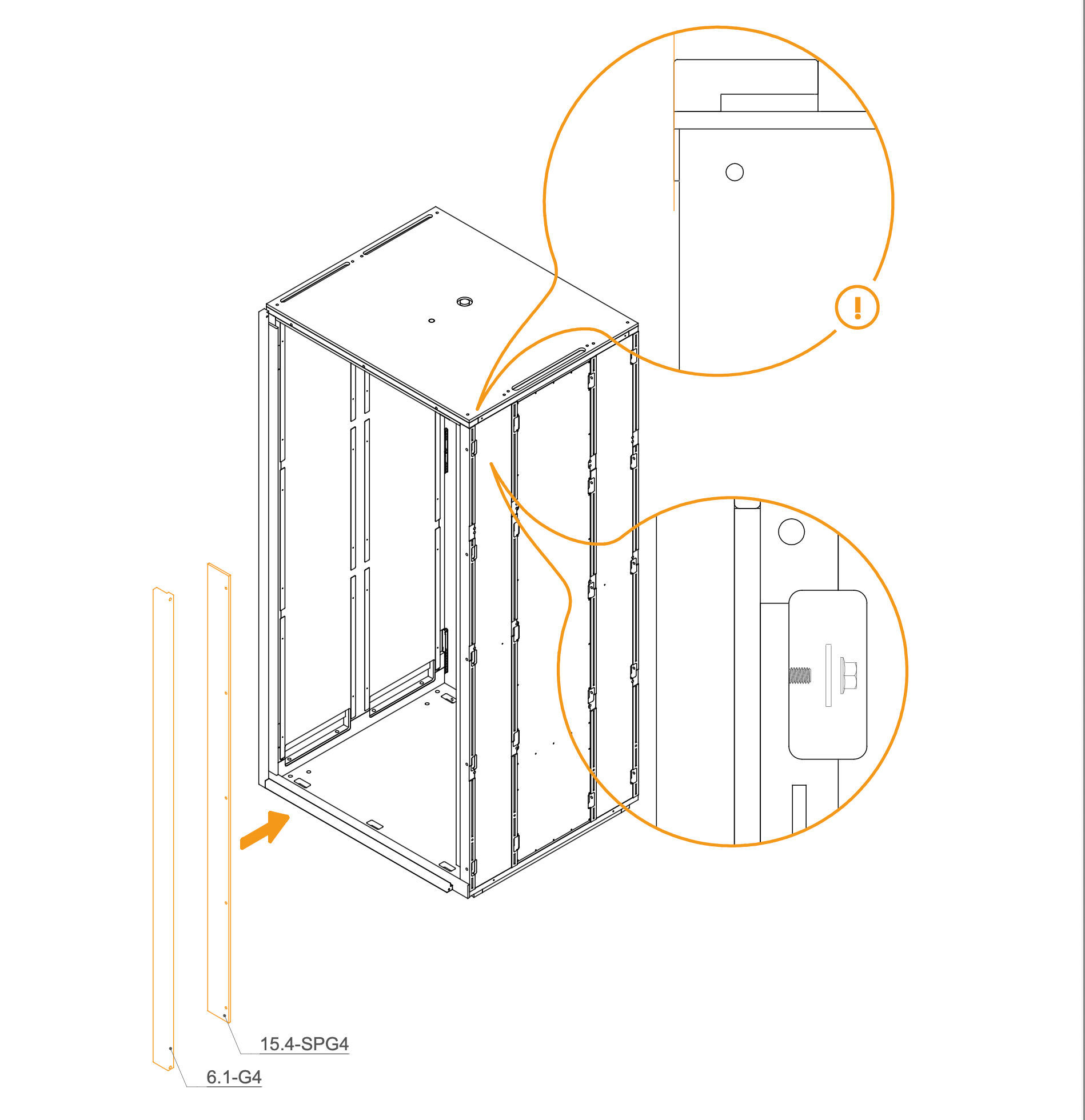
17. Attach Rear Frame to the Dock
Place the two vertical frames, 6.1-G4 and 15.04-SPG4, in their designated positions.
Secure each frame by inserting a washer (T0198) and tightening an M6 flange nut (T0514) onto the threaded rod in the slot openings.
Ensure the frames are properly aligned before fully tightening the nuts.
Parts used:
Flange nut M6 | T0514 | 5×
Washer 8.4×24×2.0 mm | T0198 | 5×
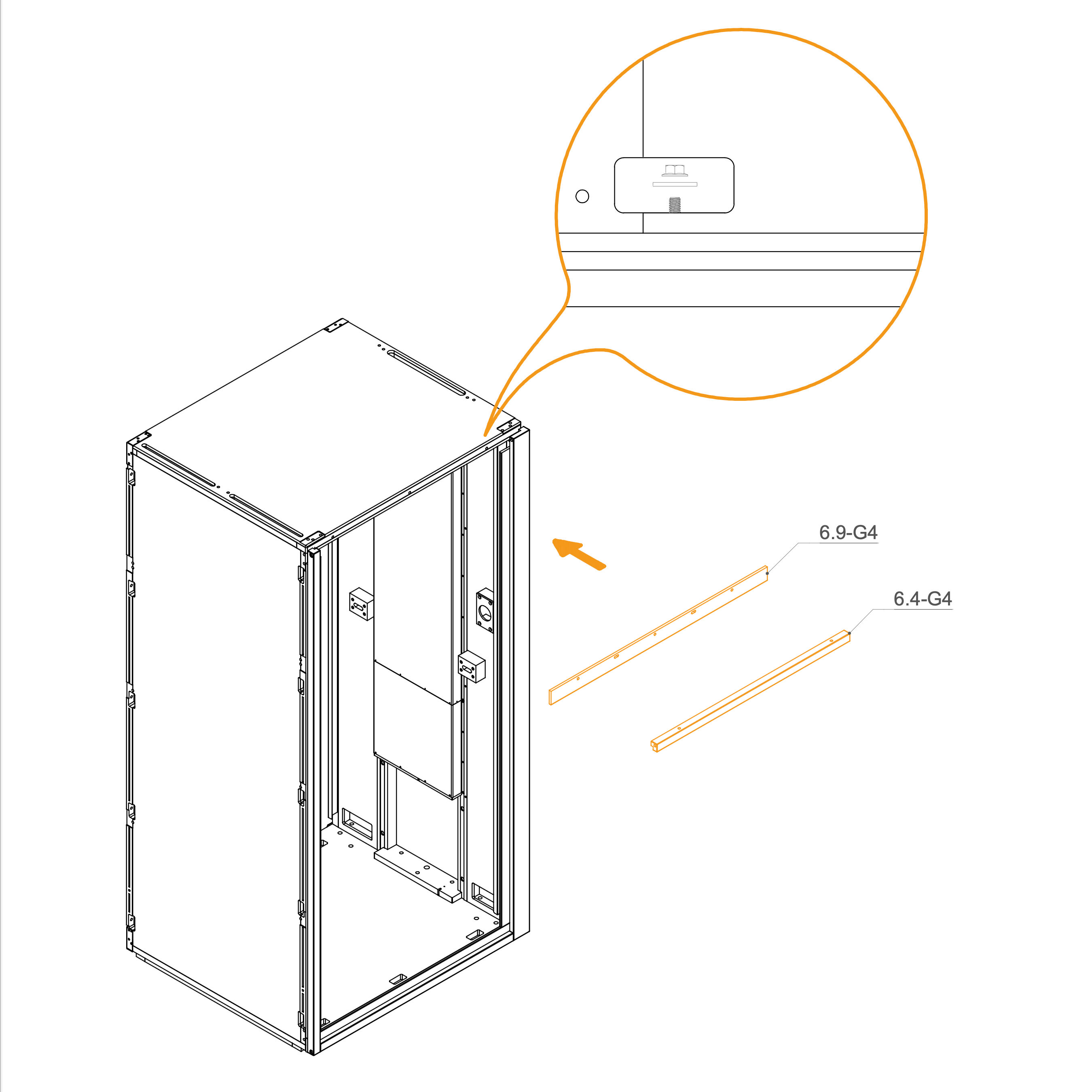
18. Attach Rear Frame to the Roof
Identify parts 6.9-G4 and 6.4-G4.
Place the frame at the top of the rear frame, aligning them with the corresponding holes.
Secure the profile using M6 flange nuts (T0514) and washers (T0198) as indicated.
Parts used:
flange nut M6 | T0514 | 3×
washer 8.4×24×2.0 mm | T0198 | 3×
19. Ensure the frames are aligned
Align each profile as shown.
20. Attach the Threaded Rod to Front Frame
Place the M6×90 mm threaded rod (T0547) into 1x 6.4-SPG4 Frame.
Insert M6×50 mm threaded rod (T0515) into the 1x 6.4-SPG4, 1x 6.4-G4, 1x 6.4-SPG4 Frame.
Parts used:
M6x50 mm screw | T0515 | 13×
M6x90 mm screw | T0547 | 3×
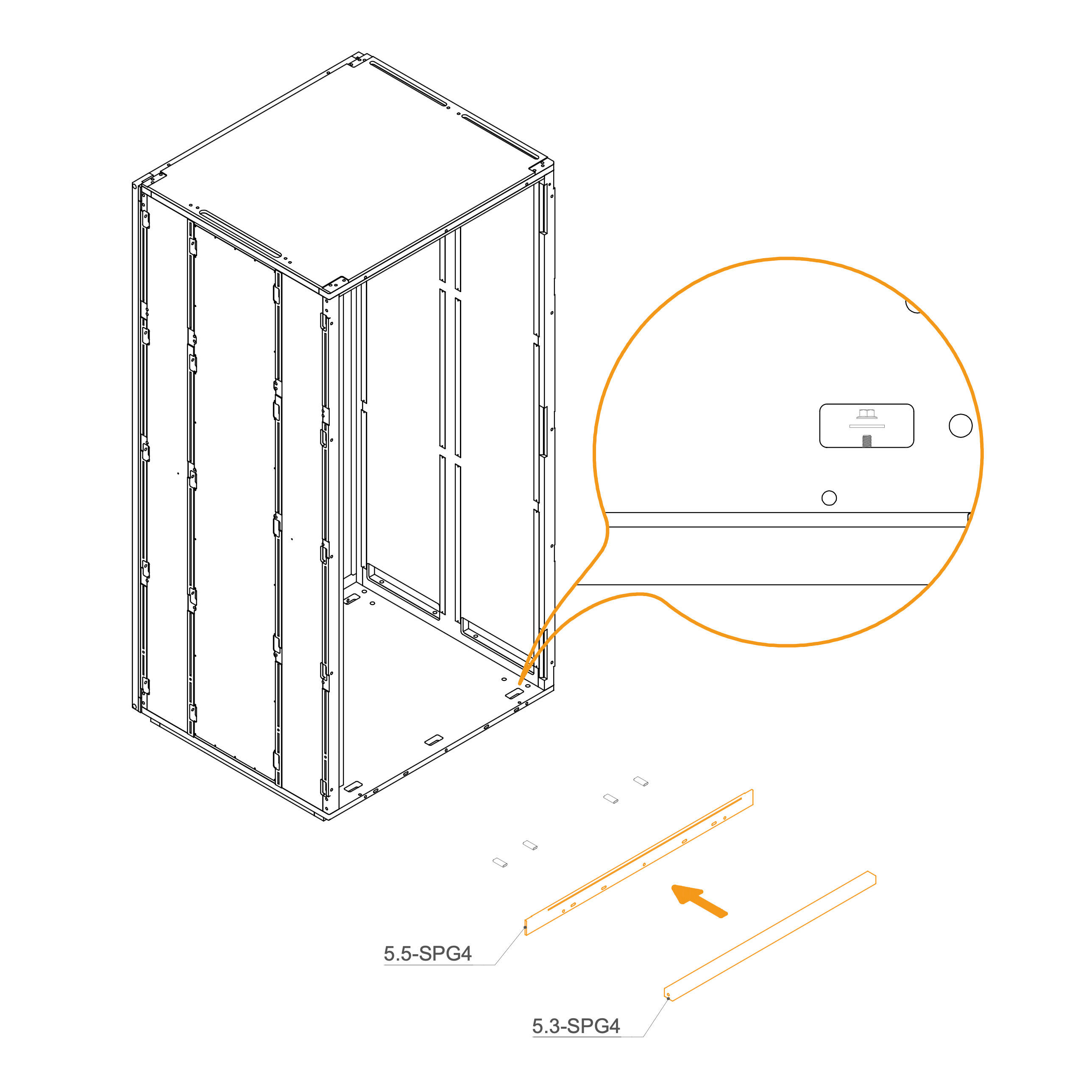
21. Attach Front Frame to the Floor Panel
Insert the two lower front rails (5.3-SPG4 and 5.5-SPG4) into position at the front base of the structure.
Align the holes on both parts with the openings in the floor panel.
Slide four spacers (T0536) into the designated slots between the rails and the floor.
From the interior, secure the assembly with three M6 flange nuts (T0514) and three washers (T0198).
Tighten all nuts using a 10 mm reversible ratchet wrench to ensure a solid connection.
Parts used:
flange nut M6 | T0514 | 3×
washer | T0198 | 3×
dowel pin D8×50×22 mm | T0536 | 4×
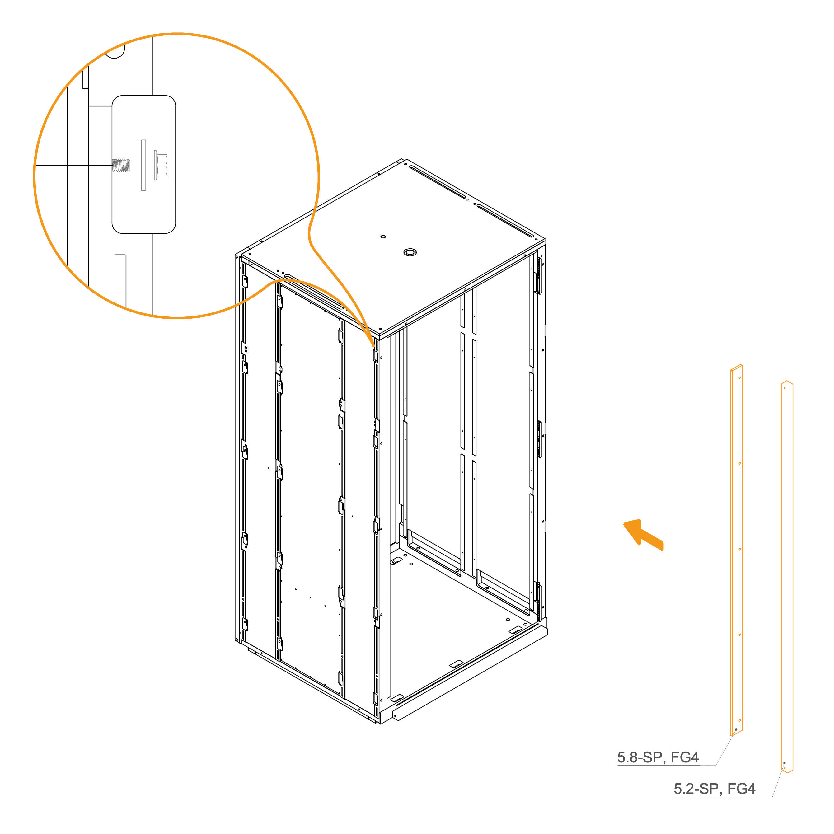
22. Attach Front Frame to Wall Panel
Place the vertical frame 15.05-G4 and 6.2-G4 into their respective positions.
Secure the frame by inserting a washer (T0198) and tightening an M6 flange nut (T0514) onto the threaded rod in the slot openings.
Ensure the frame is properly aligned before fully tightening the nuts.
Parts used:
washer 8.4×24×2.0 mm | T0198 | 5×
flange nut M6 | T0514 | 5×
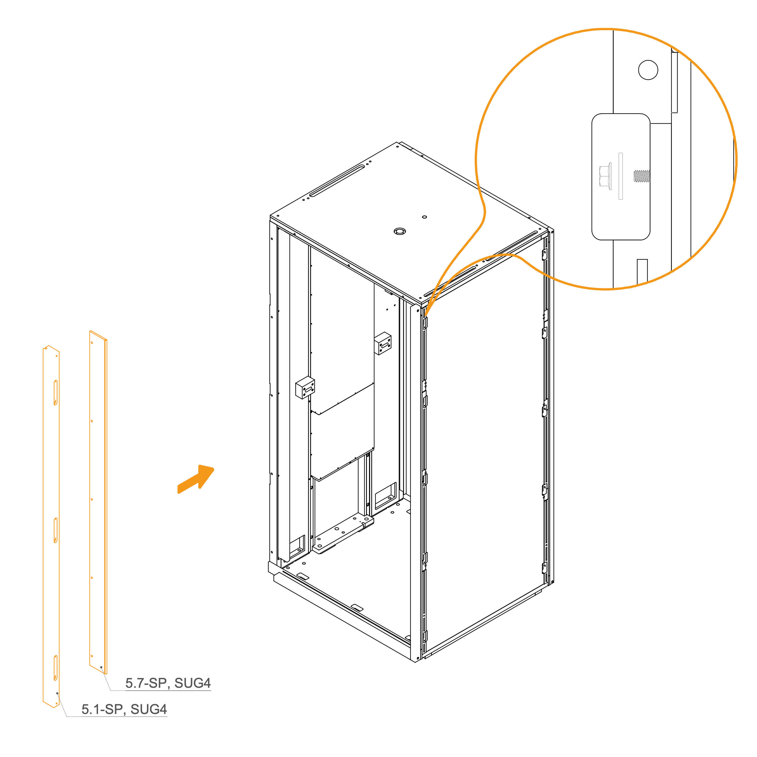
23. Attach Front Frame to Dock
Place the vertical frame 5.1-SP,SUG4 and 5.7-SP,SUG4 into their respective positions.
Secure the frame by inserting a washer (T0198) and tightening an M6 flange nut (T0514) onto the threaded rod in the slot openings.
Ensure the frame is properly aligned before fully tightening the nuts.
Parts used:
washer 8.4×24×2.0 mm | T0198 | 5×
flange nut M6 | T0514 | 5×
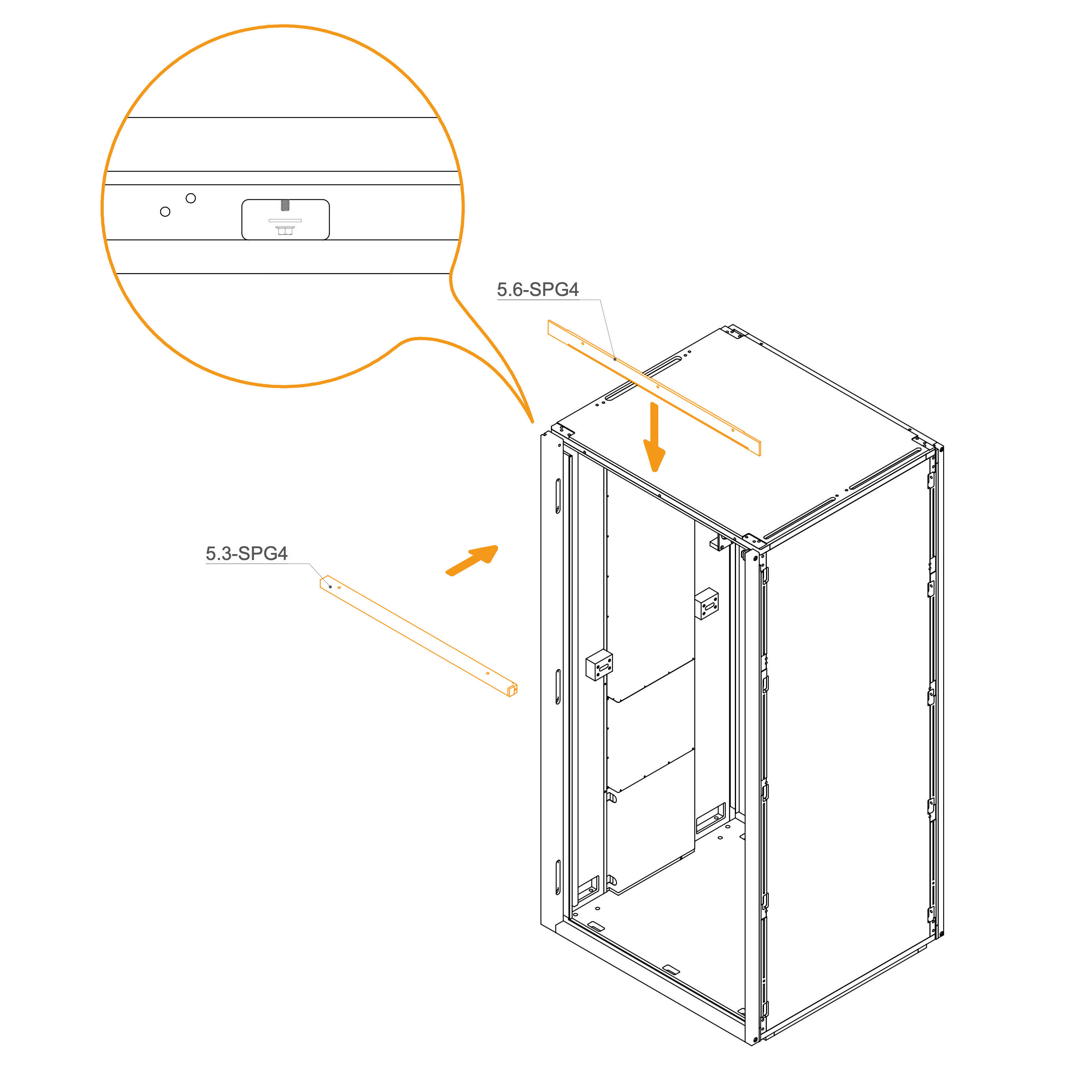
24. Attach Front Frame to the Roof
Insert both 5.3-SPG4 and 5.6-SPG4 horizontal frames, in their designated positions.
Secure each frame by inserting a washer (T0198) and tightening an M6 flange nut (T0514) onto the threaded rod in the slot openings.
Ensure the frames are properly aligned before fully tightening the nuts.
Parts used:
washer 8.4×24×2.0 mm | T0198 | 3×
flange nut M6 | T0514 | 3×
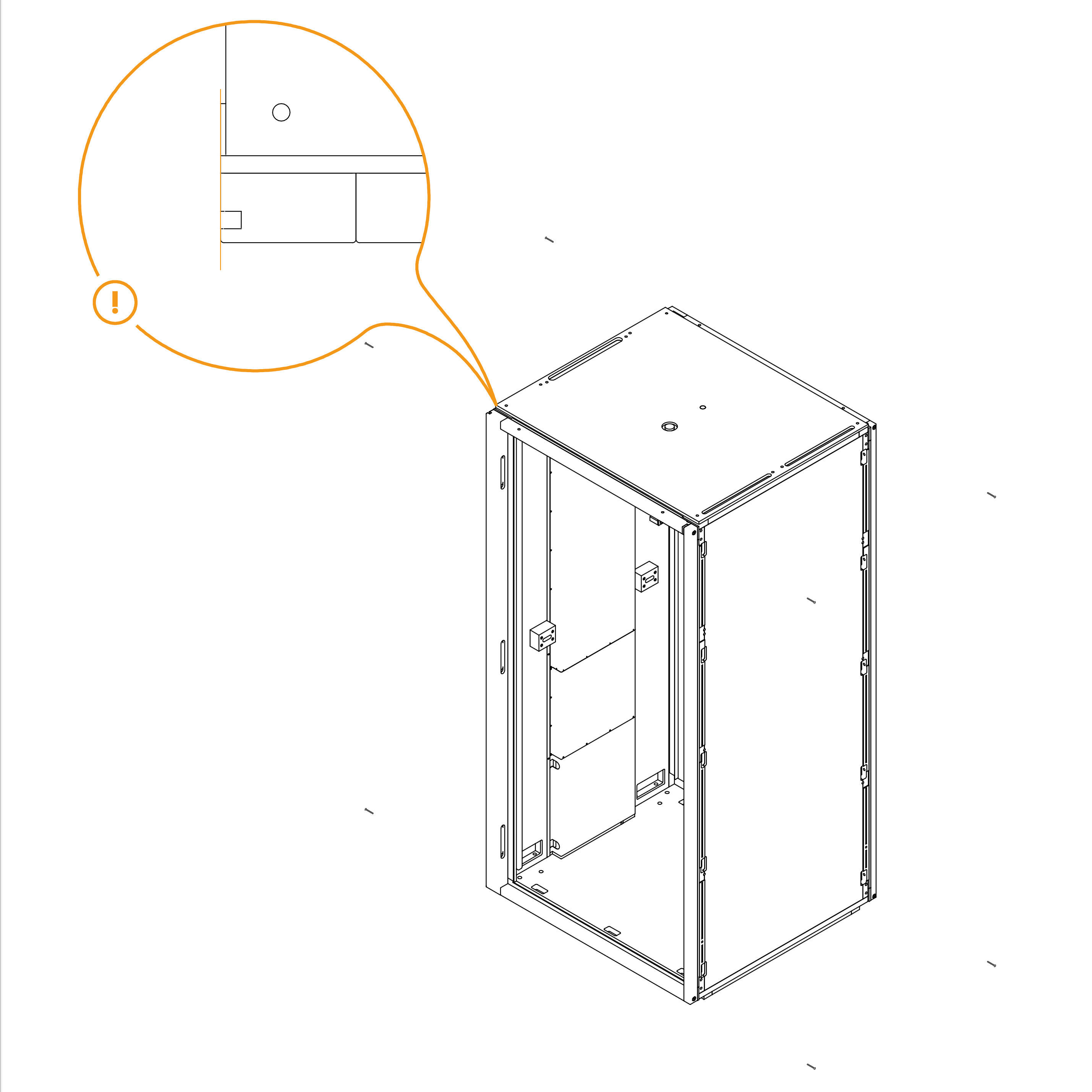
25. Ensure the frames are aligned
Align each profile as shown.
Door
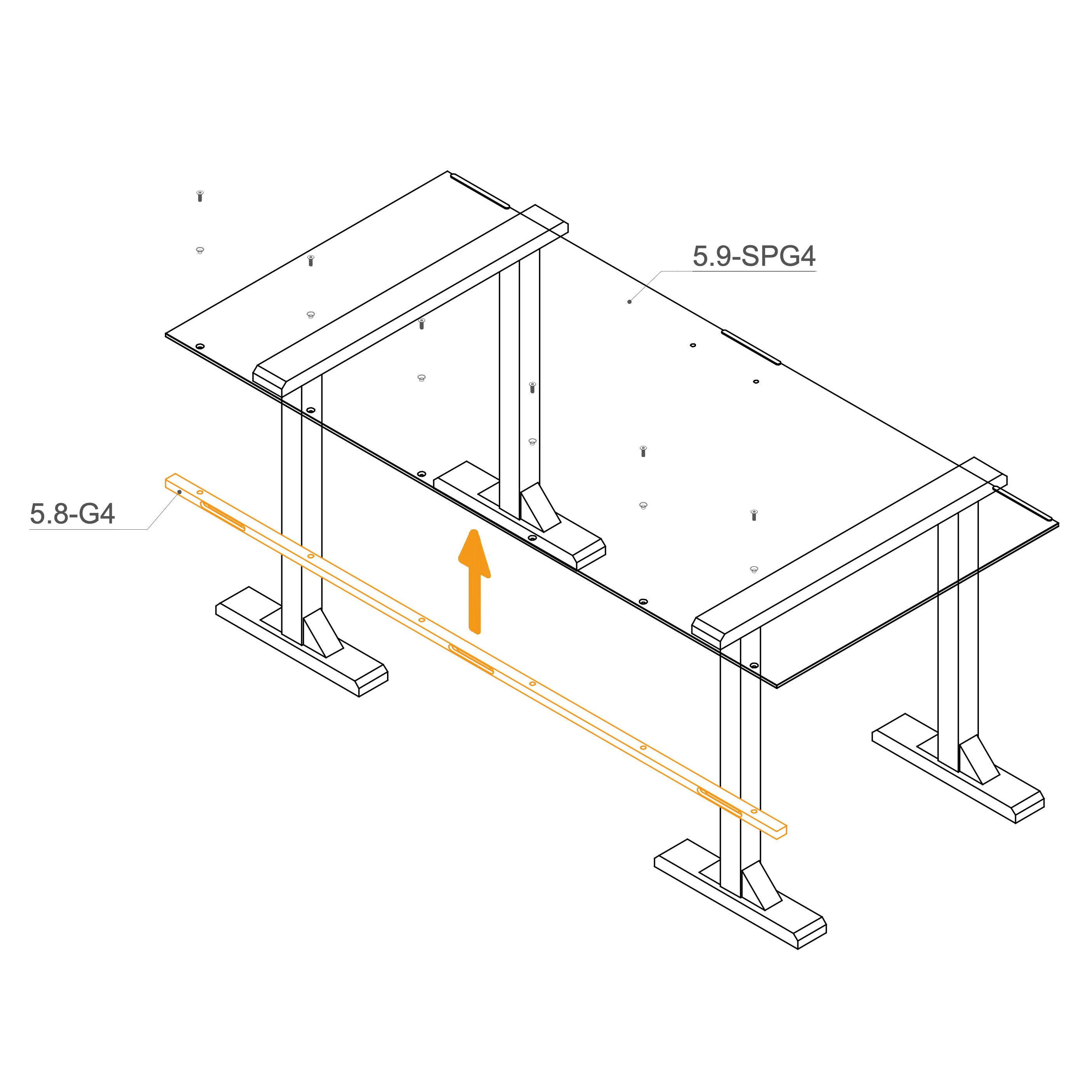
26. Fasten Frame to the Glass
Place the glass5.9-SPG4 on the working stand.
Insert the plastic insert (O0433) into the countersunk holes in the glass, and secure the frame 5.8-G4 to the glass using M8×25 mm screws (T0512).
Parts used:
M8×25 mm screw | T0512 | 6×
Insert | O0433 | 6×
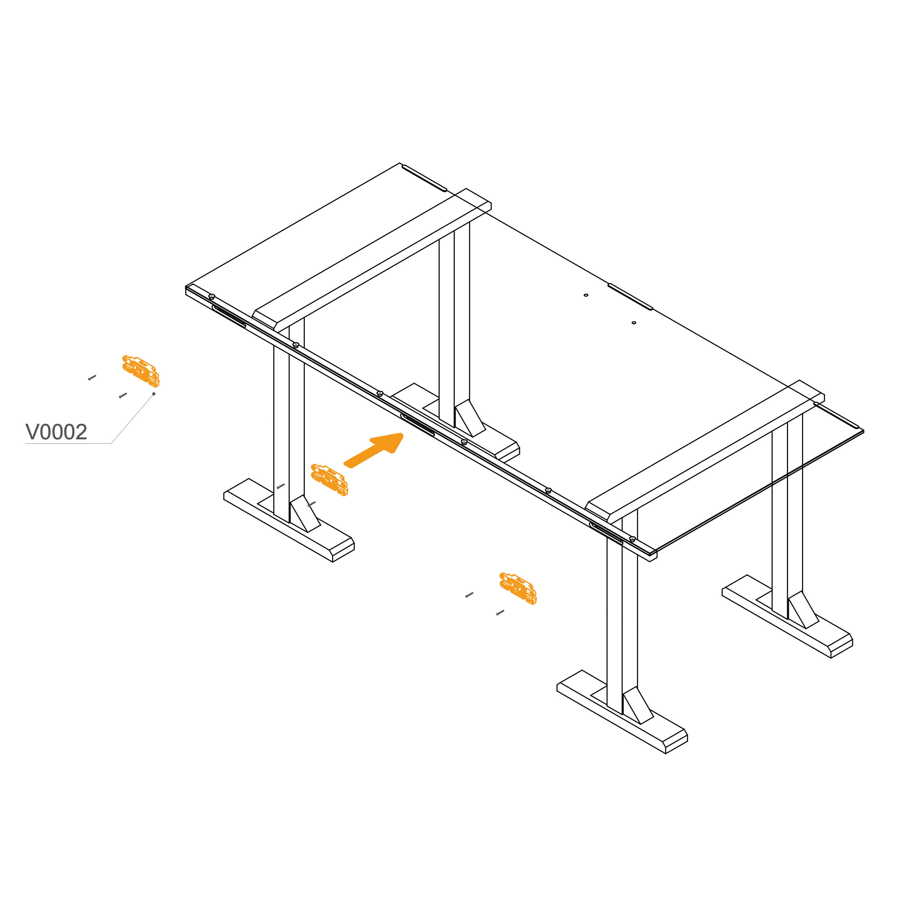
27. Mount Door Hinges
Attach hinges (V0002) into the recess use M4×30 mm screws to secure the position.
Repeat for all 3 positions as shown.
Parts used:
hinge | V0002 | 3×
M4×30 mm screw | T0070 | 6×
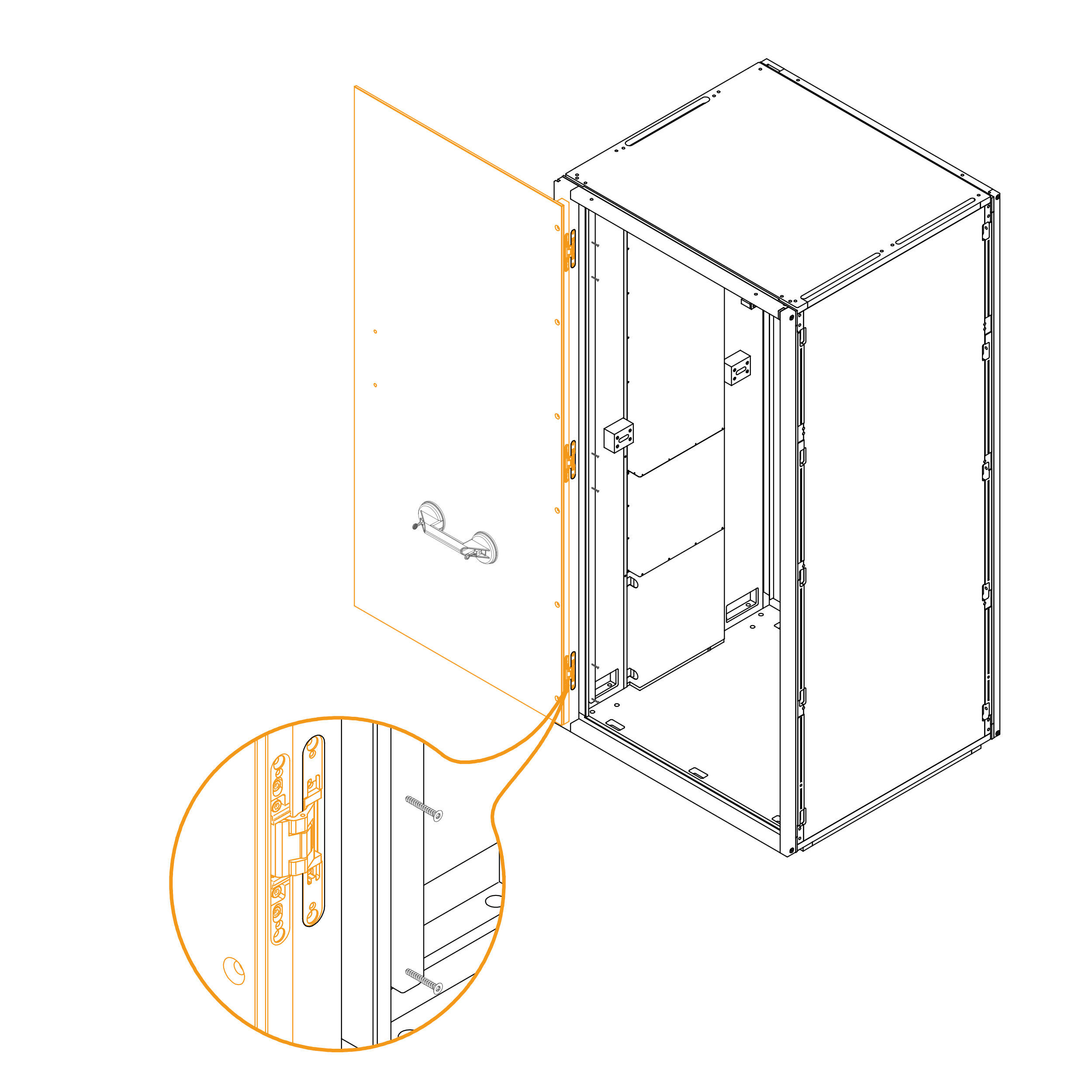
28. Secure the Door in the Frame
Place the door into the recesses in the frame and secure it with screws M4×30 mm (T0070).
Parts used:
M4×30 mm screw | T0070 | 6×
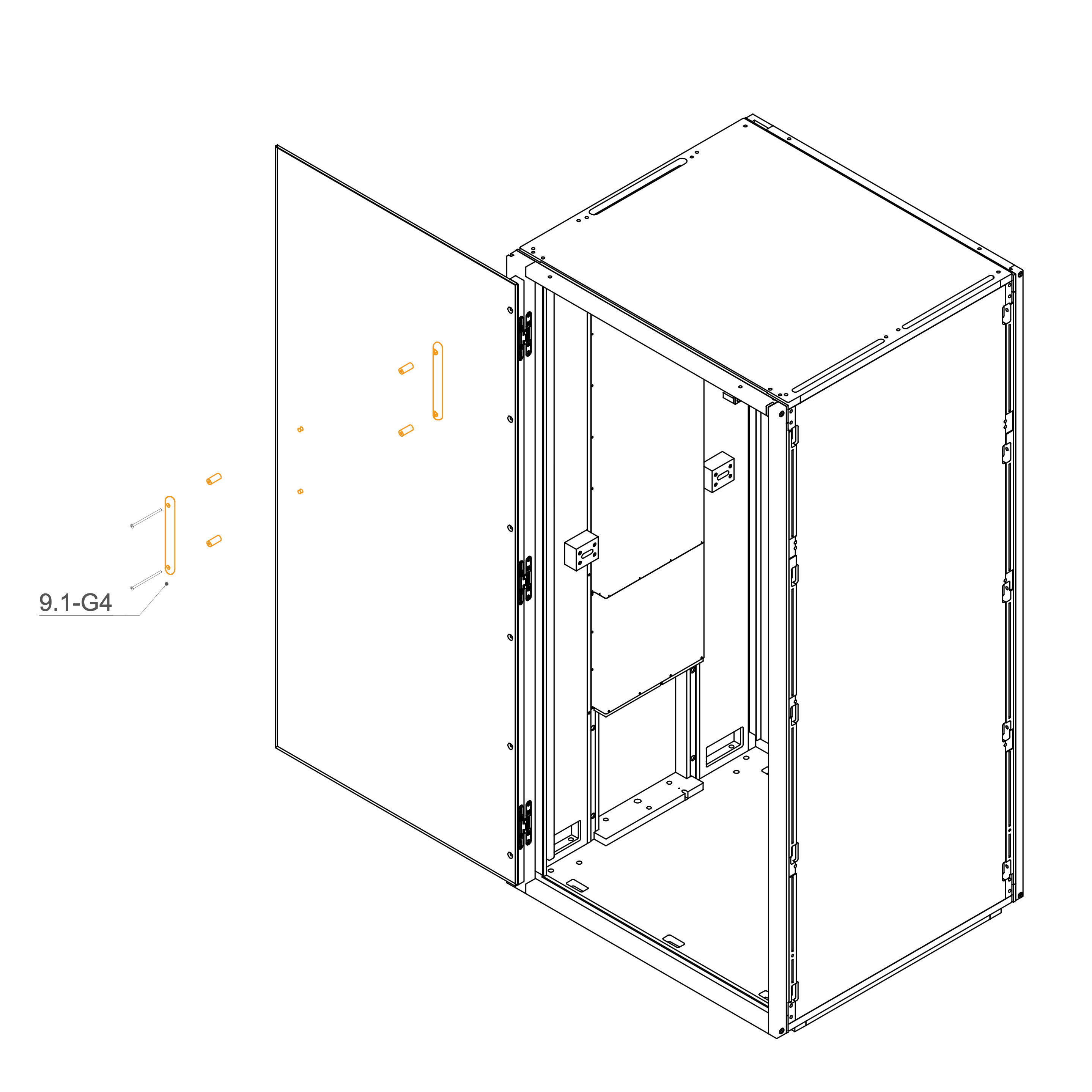
29. Install Handle
Align the two parts of the handle on either side of the hole in the glass.
Insert the enclosed M6×120 mm screw through the hole and fasten the handle parts using a 4 mm hex key.
Place the plastic spacer between the screw and the glass to prevent direct contact.
Tighten the screw securely, ensuring the handle is firmly attached without over-tightening.
Parts used:
T0530 | M6×120 mm bolt | 2×
T0097 | Spacer block 6.2×10×10 mm | 2×
Speakers
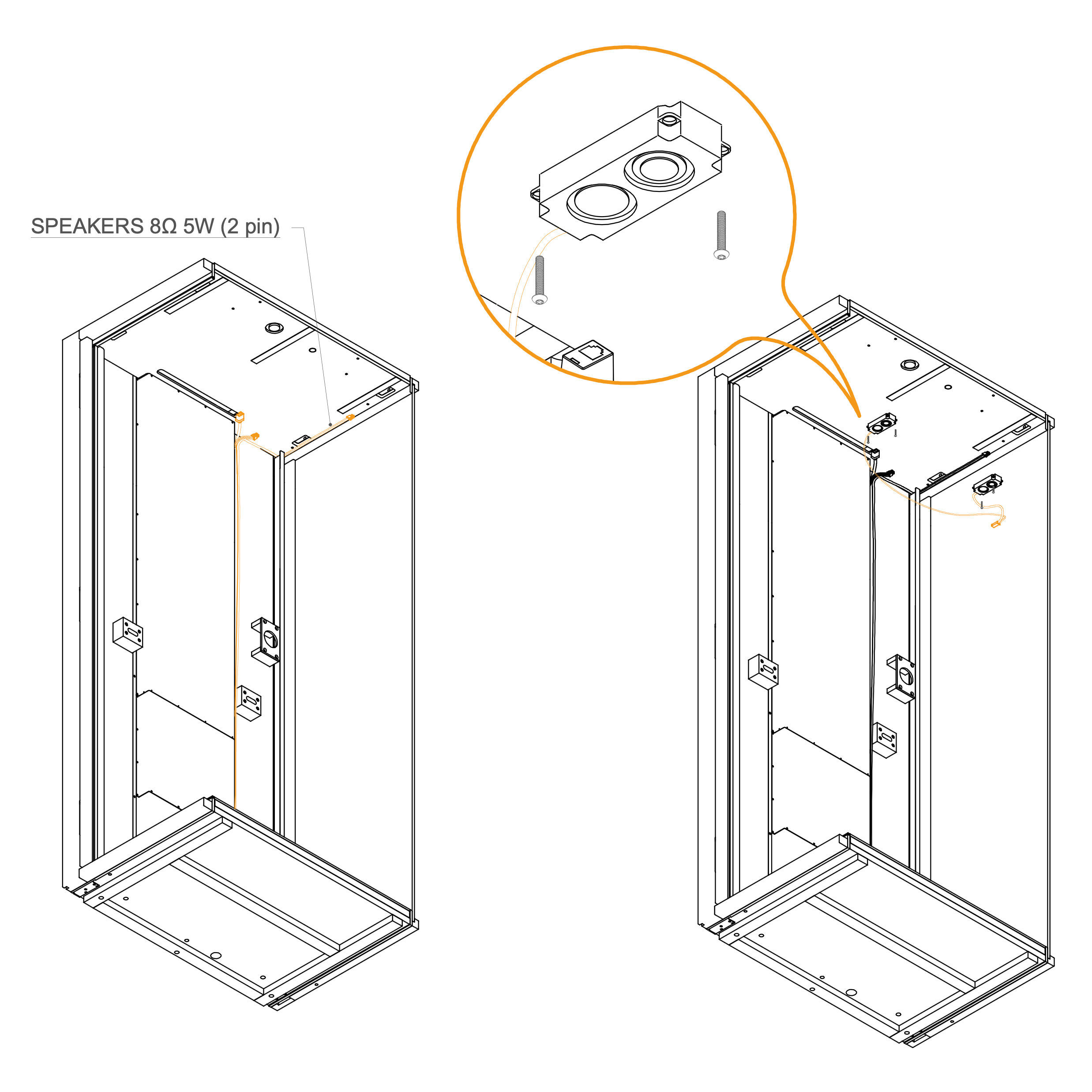
30. Install Speakers
Position the speaker modules in the predrilled ceiling holes.
Secure each speaker with two M4x10 screws (T0499).
Plug the corresponding cable SPEAKERS 8Ω 5W (2 pin) to the speakers.
Parts used:
M4×25 mm screw | T0435 | 4×
Light Installation
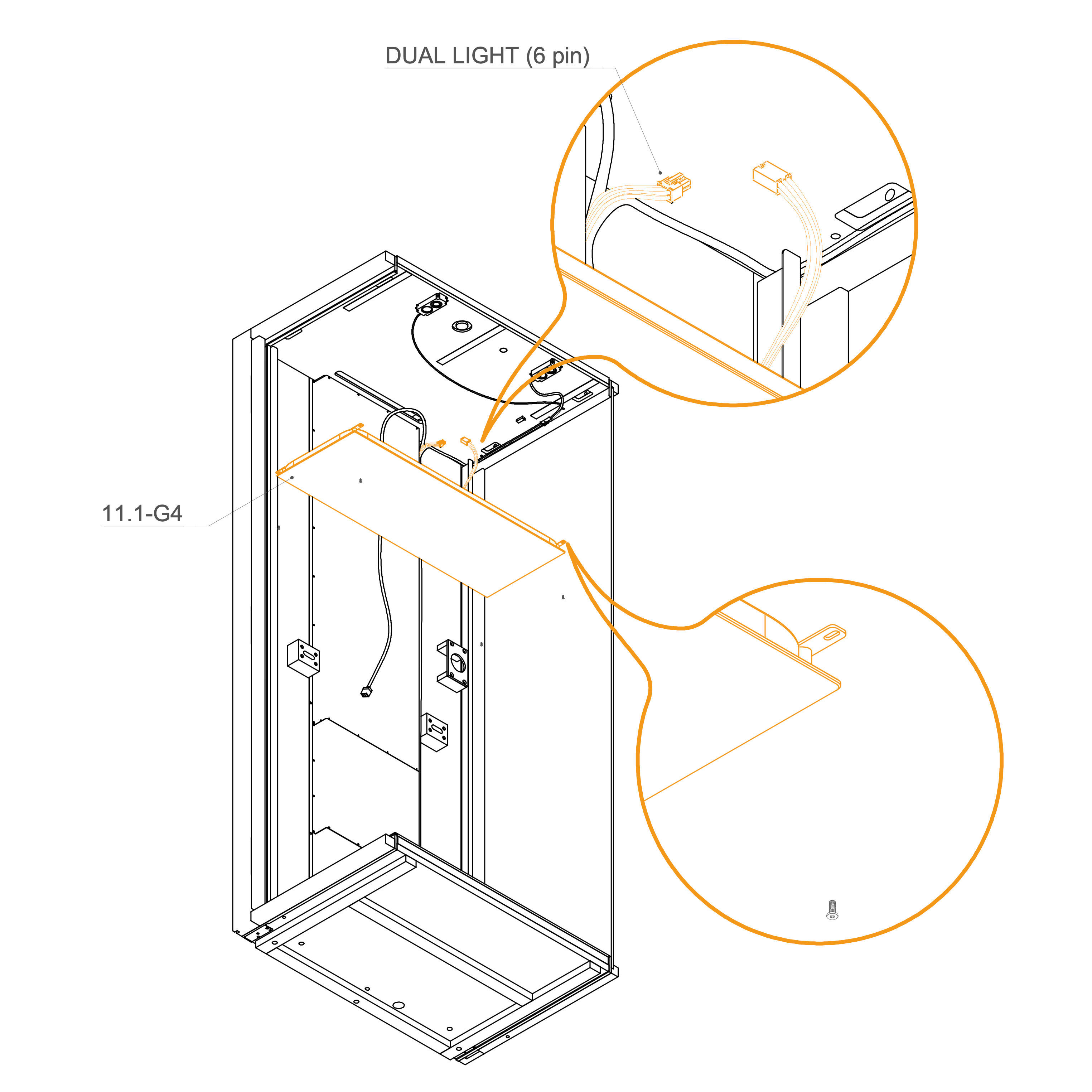
31. Install Light
Connect the PIR sensor cable (RJ11) and the dual light cable (6 pin).
Position and secure the light panel to the ceiling using screws.
Parts used:
M4×10 mm screw | T0499 | 4×
External Panels
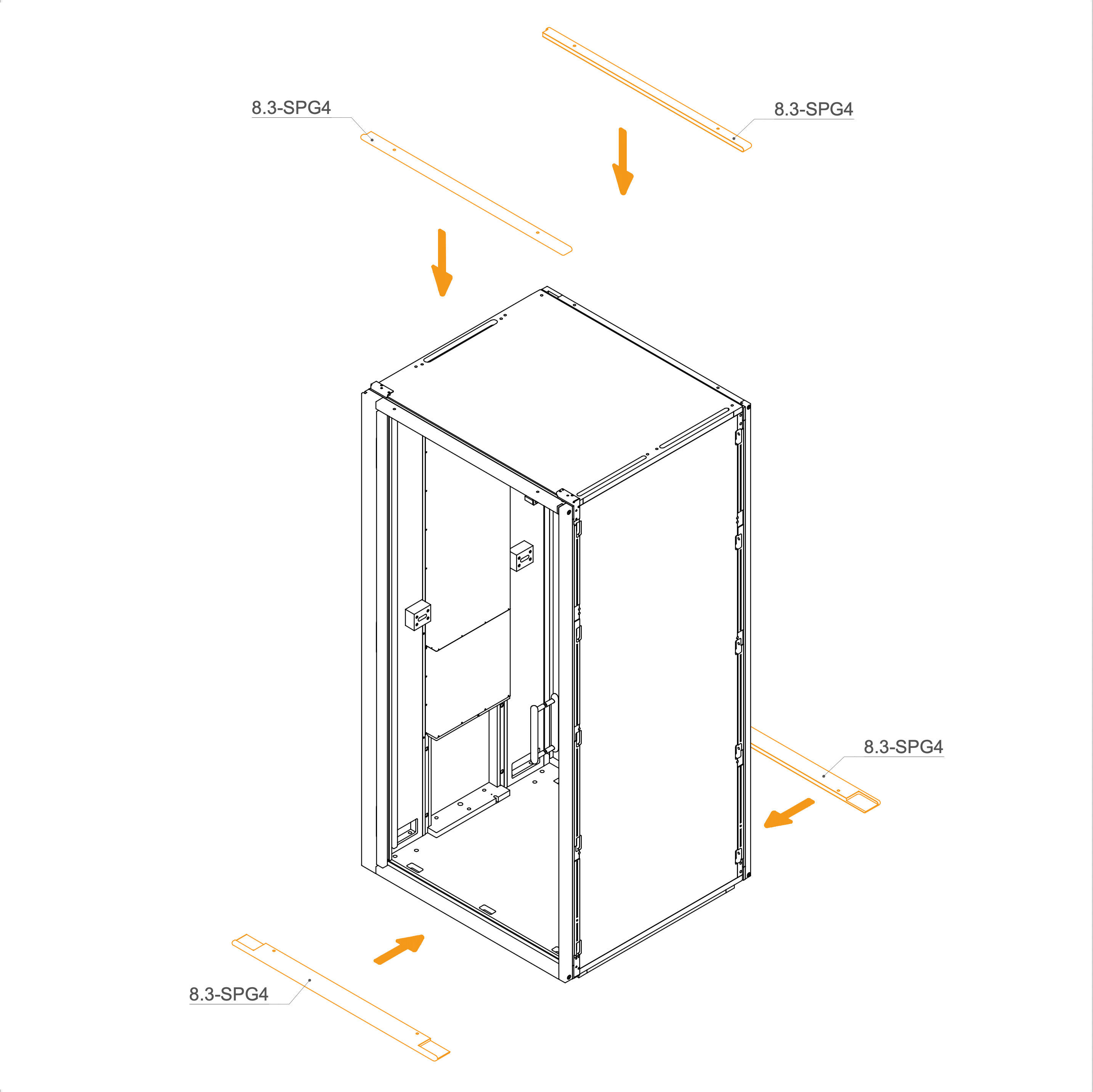
32. Attach external panels
Install the upper panels 8.3-SPG4 by aligning them with the edge of the frame and the screw holes.
Prepare the lower panels 8.2-SPG4 by positioning them underneath the frame. You may use spacers or supports to make fastening easier.
Parts used:
external panel | 8.3-SPG4 | 2x
external panel | 8.2-SPG4 | 2x
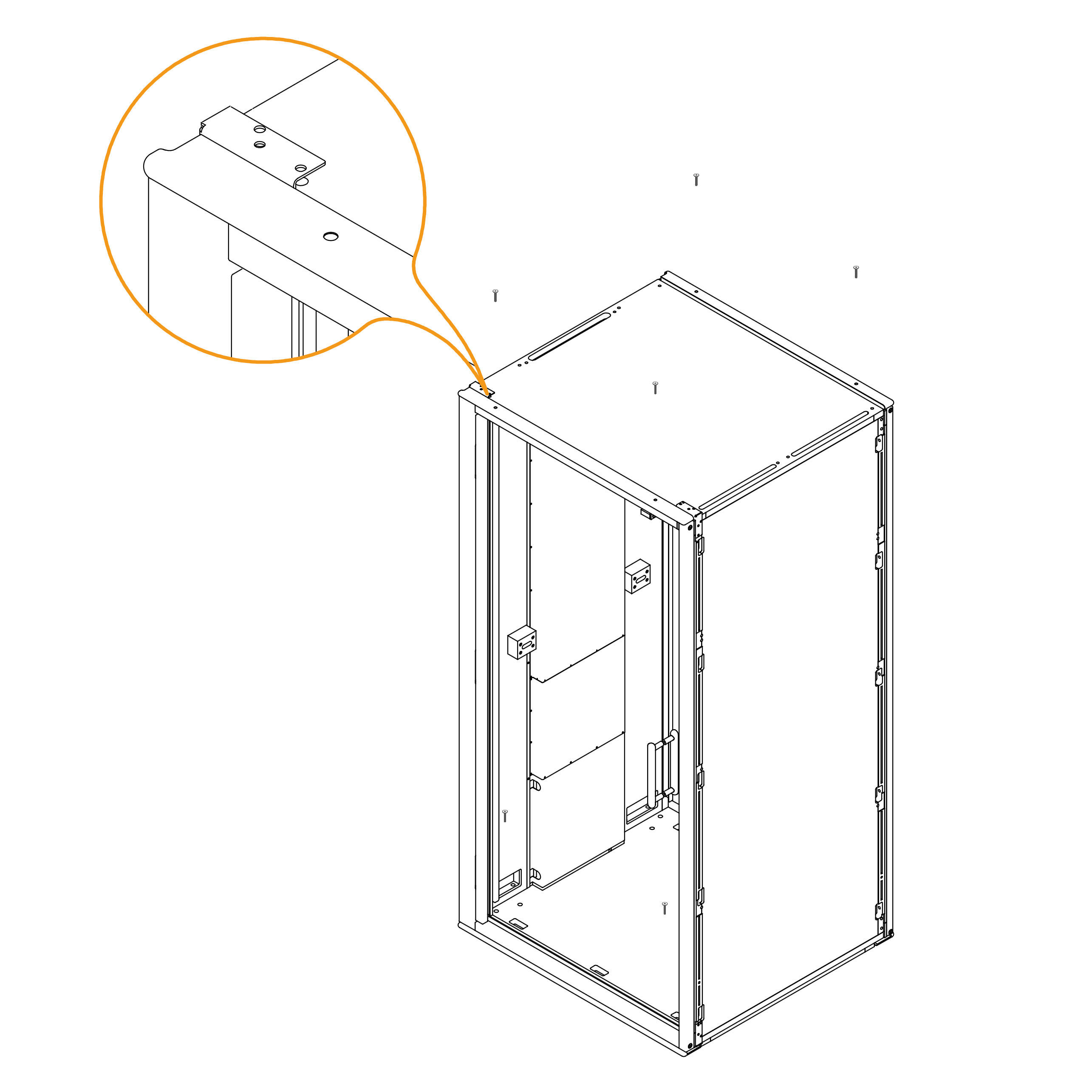
33. Fix the External Panels
Secure the previously placed external panels using screws (T0397).
Parts used:
T0397 | M6×40 mm screw | 8×
Floor Isolation
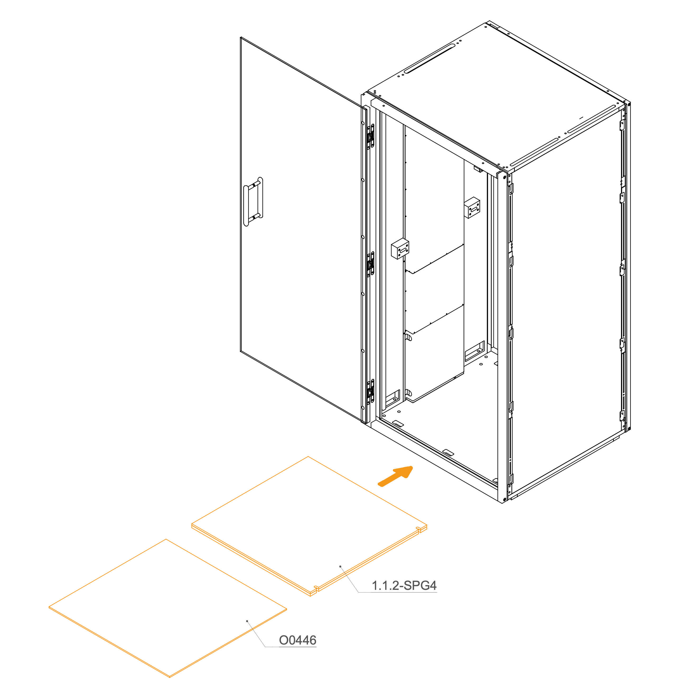
34. Place Floor Isolation and Carpet Inside the Pod
Insert the floor insulation (1.1.2-SPG4) into the bottom frame of the pod. Ensure the notches align with the internal structure for a proper fit.
Place the carpet (O0446) on top of the floor isolation panel. Make sure it lies flat and flush with the walls.
Parts used:
Floor isolation panel | 1.1.2-SPG4 | 1×
O0446 | Carpet | O0446 | 1×
Table Brackets
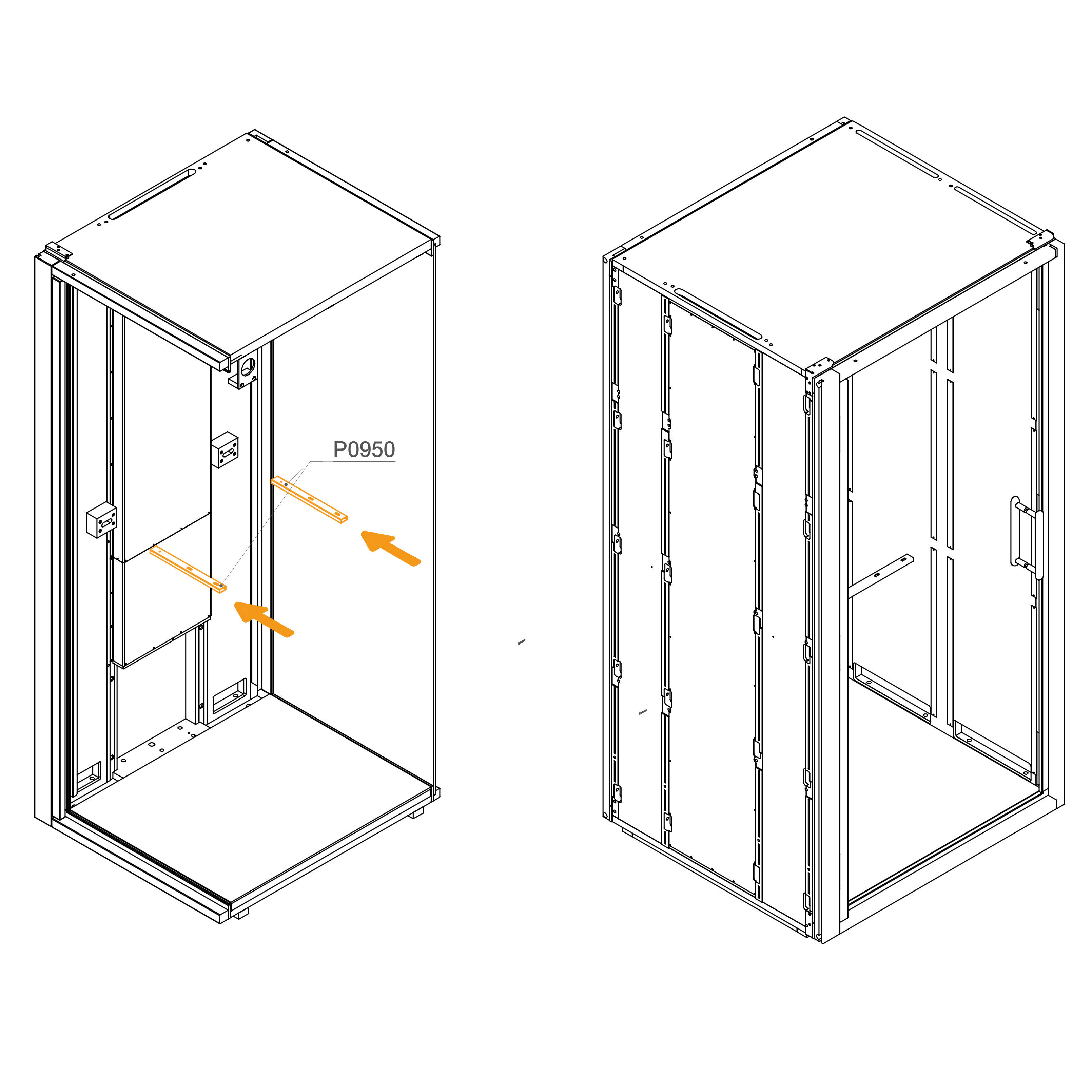
35. Install Table Holder
Insert table holder into the wood bracing (P1240)
Parts used:
table holder | P0950 | 2×
Interior Panels
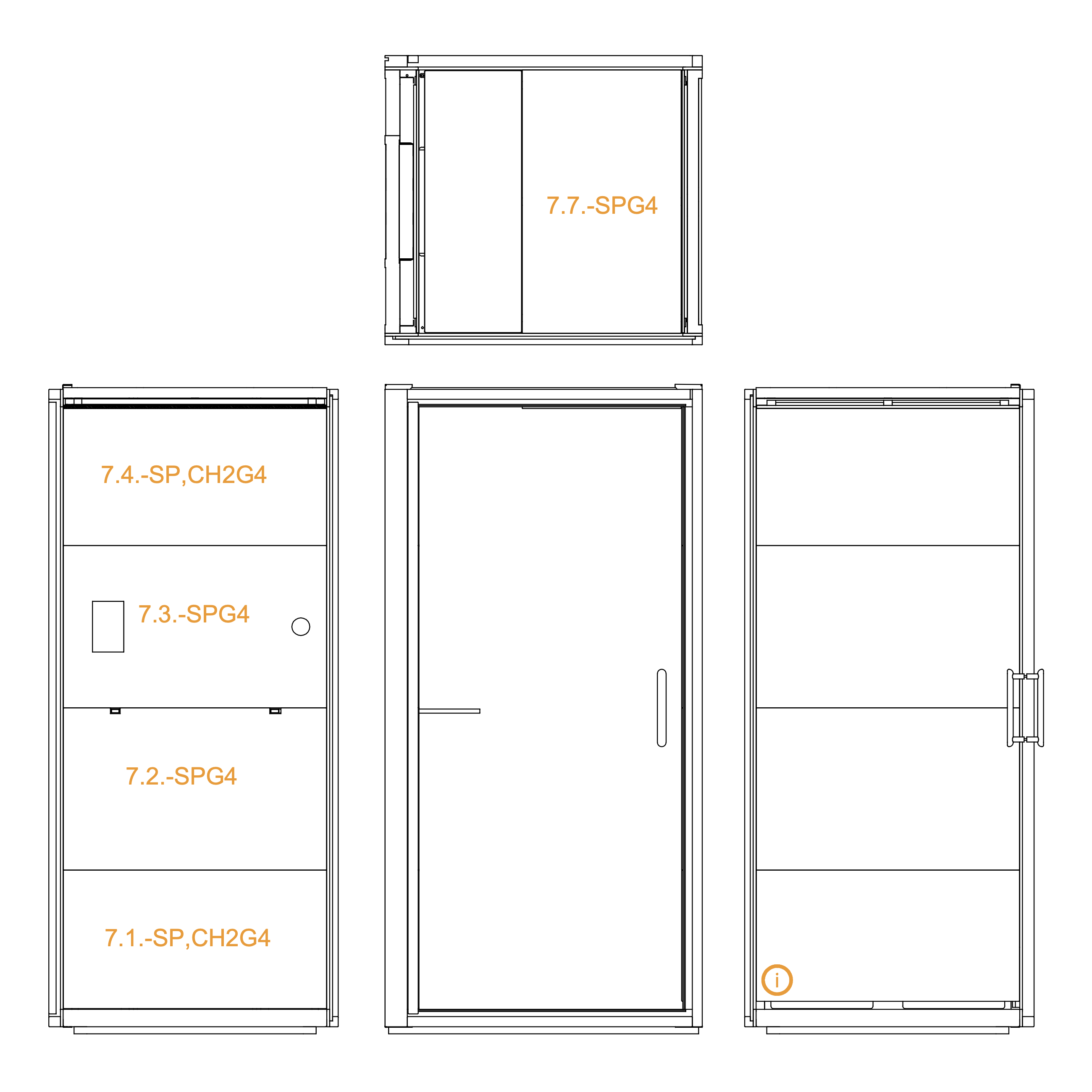
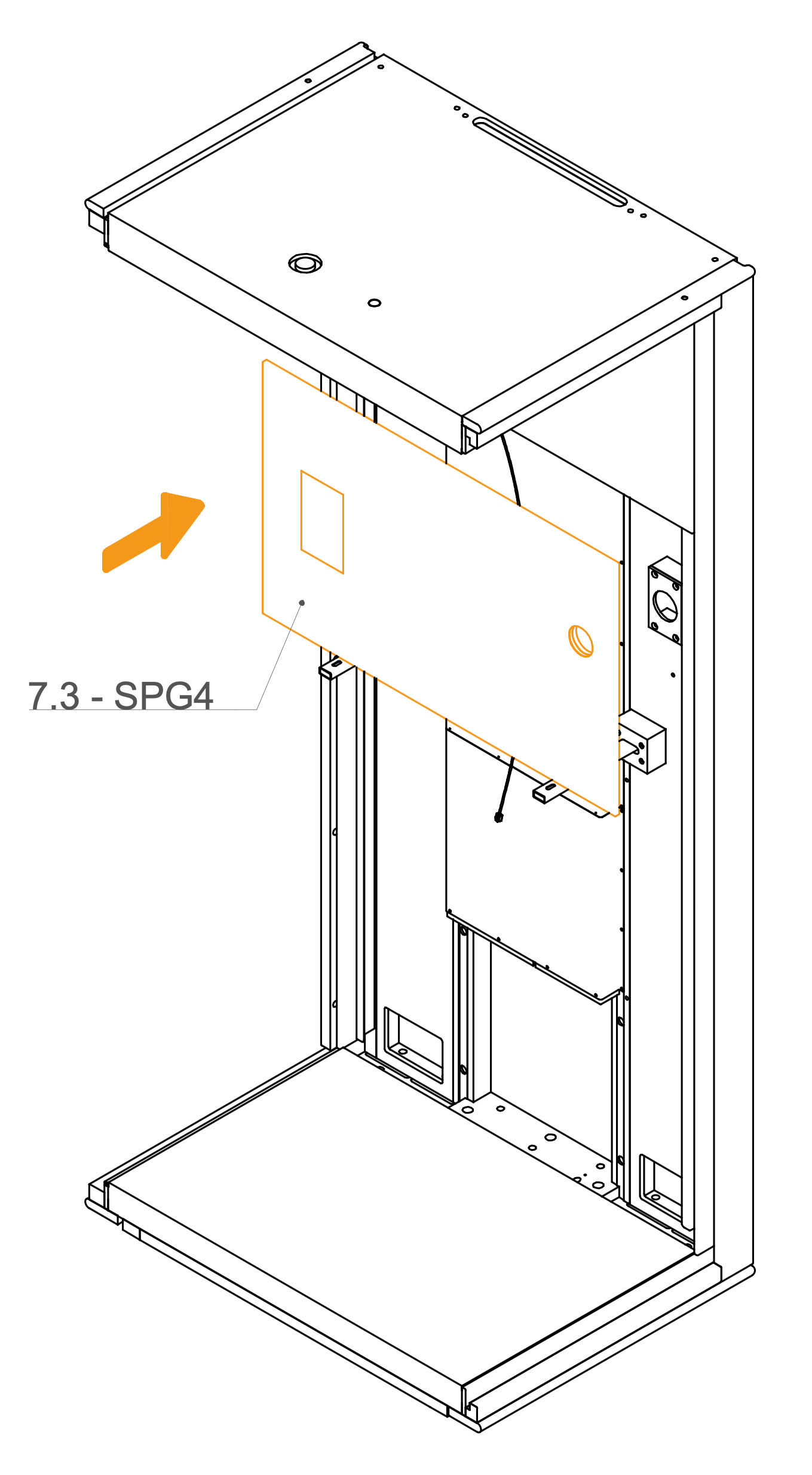
36. Install Interior Wall and Ceiling Panels
Position the labeled interior panels (as per the diagram) in their designated locations inside the accoustic pod.
Do not position panel 7.3-SPG4 yet.
Parts used:
interior panel | 7.4-SP_CH2G4 | 2×
interior panel | 7.5-SP_CH2G4 | 1×
interior panel | 7.6-SPG4 | 3×
interior panel | 7.7-SPG4 | 1×
interior panel | 7.8-SPG4 | 1×
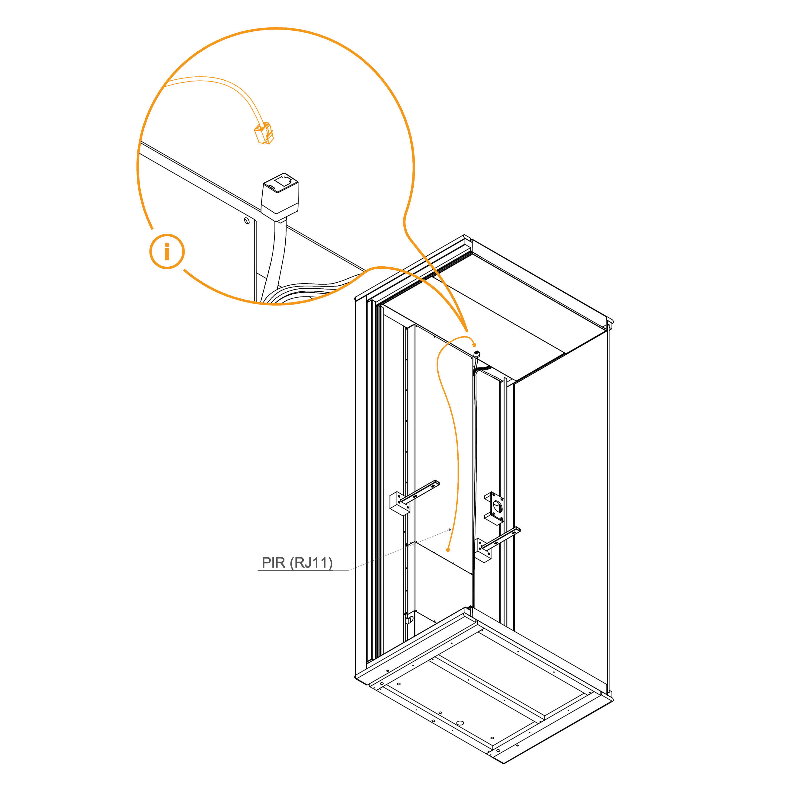
37. PIR Sensor Cable
Depending on the position of the sensor, we either leave the cable in the upper position so that it protrudes from
beneath the interior panel, or pull it down to the level of the table.
Parts used:
RJ11 connector | 1×
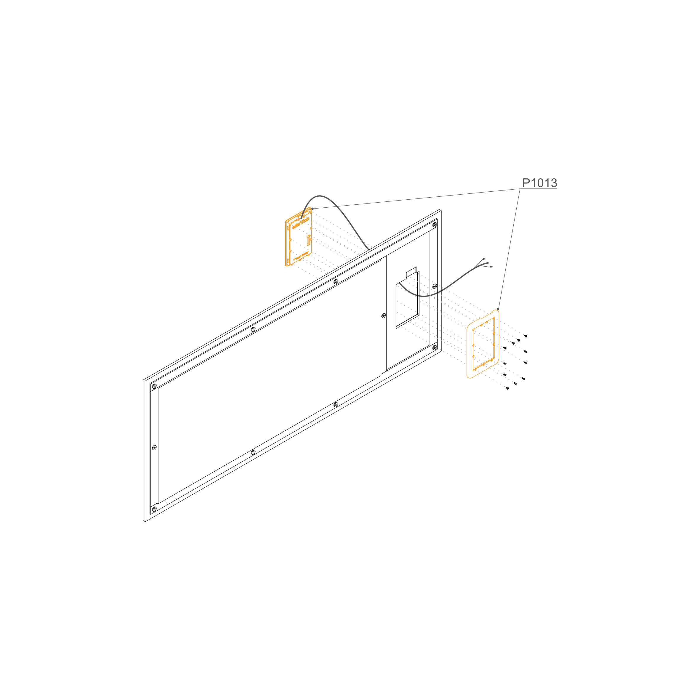
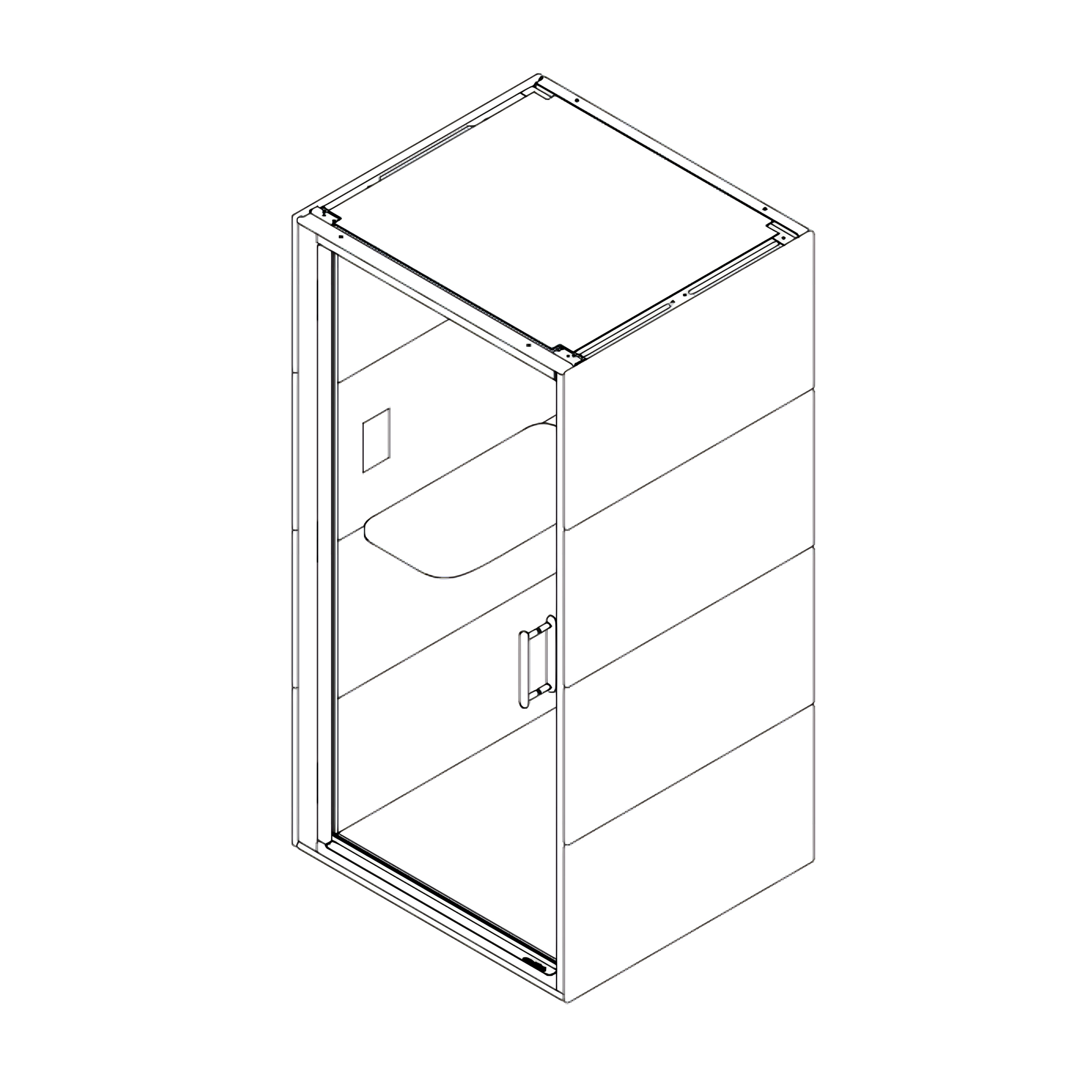
38. Insert Display into the Interior Panel
Unpack the Components: Carefully open the packaging and identify the display unit (P1013)
Disassemble the Housing: Using a screwdriver with a Torx bit, remove the rear frame from the display unit to prepare it for mounting.
Feed the Cables: Locate the cutout in the upholstered internal panel. Gently pull all display cables through the hole from the front (upholstered side) to the back.
Note: Ensure the cables are oriented upwards as shown in the diagram.
Seat the Display: Insert the display unit into the cutout on the upholstered side of the panel until it sits flush against the surface.
Mount the Rear Frame: From the back of the panel, align the rear frame (P1013) with the back of the display unit.
Fasten the Bolts: Insert the provided bolts through the frame and into the display housing. Tighten them securely to sandwich the upholstered panel between the display and the rear frame.
Note: The upholstered panel shown is for illustration only. Additional holes may be present to accommodate potential socket installations.
39. Install Socket
Connect the socket to the prepared cable in the dock. Insert the socket into the interior panel and place the panel into position. Use a screwdriver to tighten the socket and attach the cover.
Parts used:
Panel | 7.3-SPG4 | 1×
Socket | 1x
Table Panel
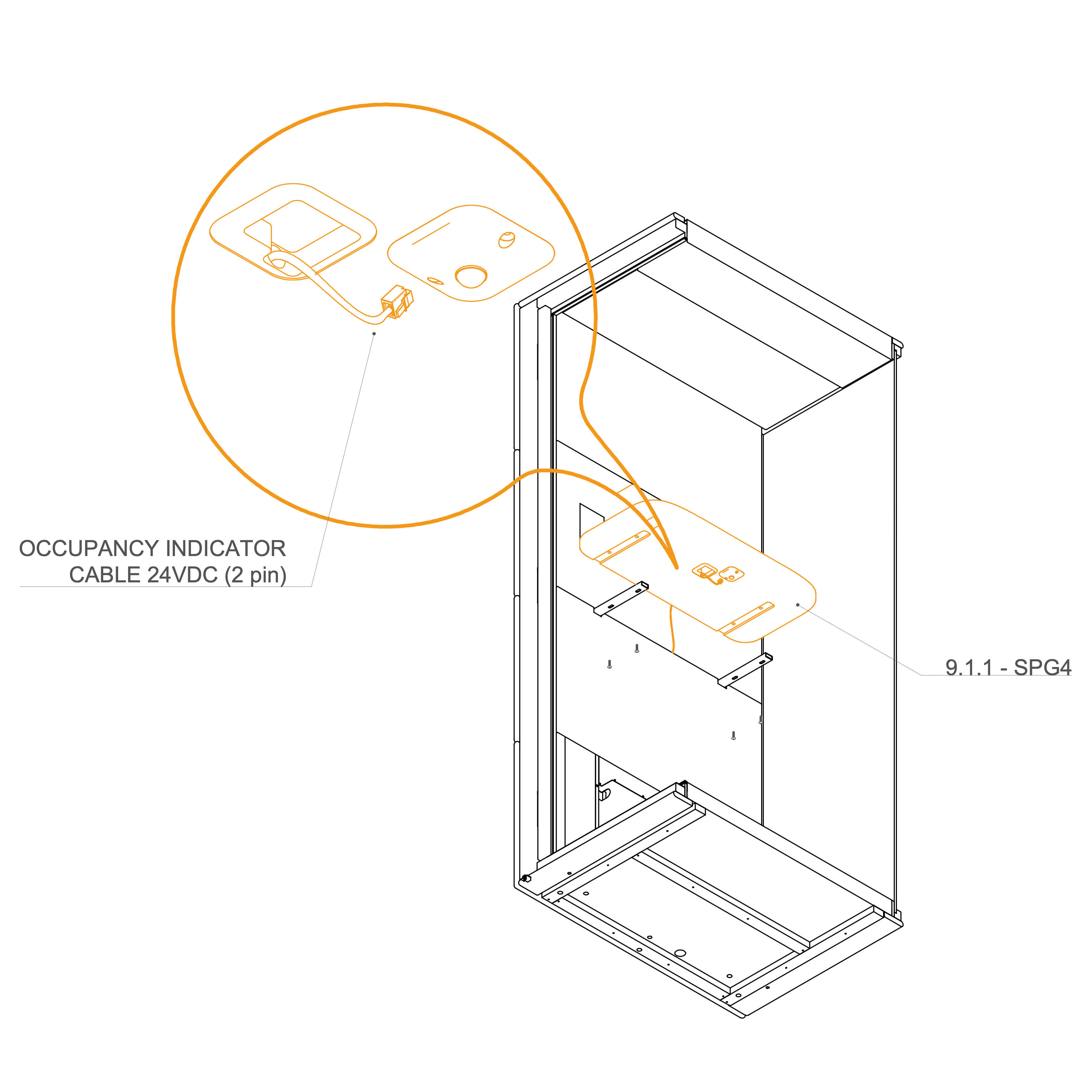
40. Install Table
Route the occupancy indicator cable 24VDC (2pin) through the hole in the desk and connect it to the sensor. Anchor the desk into the prepared holders.
Parts used:
table | 9.1.1-SPG4 | 1×
M6×25 mm screw | T0434 | 4×
occupancy indicator cable 24VDC (2pin) | 1×
External Panels
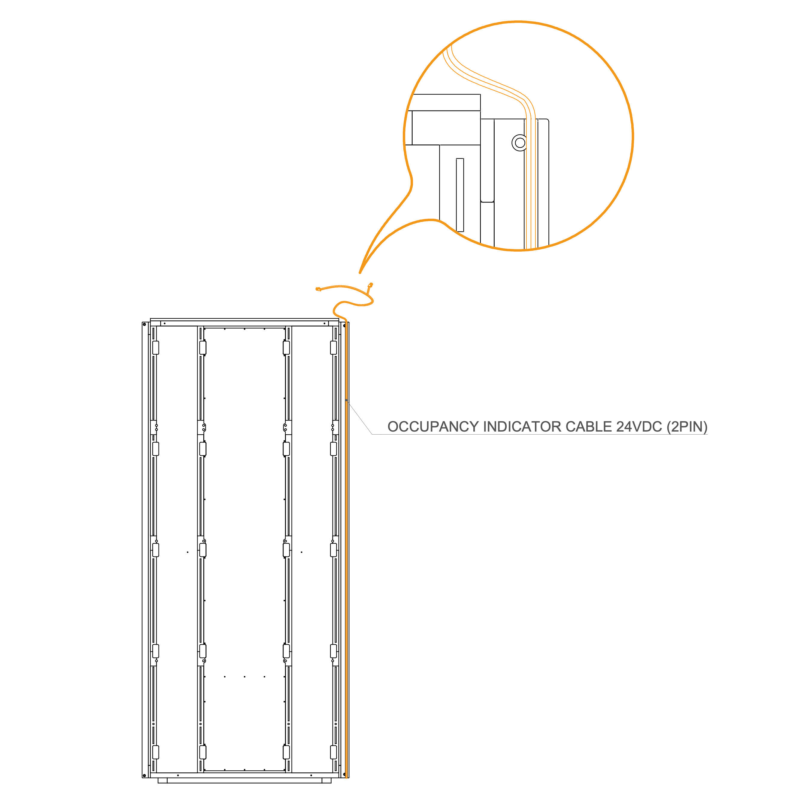
41. Install occupancy light cable
Route the GEN4_ELEKTRO_CABLE OCCUPANCY SIGNALIZATION 4600 mm (E0816) in the groove as shown.
Parts used:
GEN4_ELEKTRO_CABLE OCCUPANCY SIGNALIZATION 4600 mm | E0816 | 1×
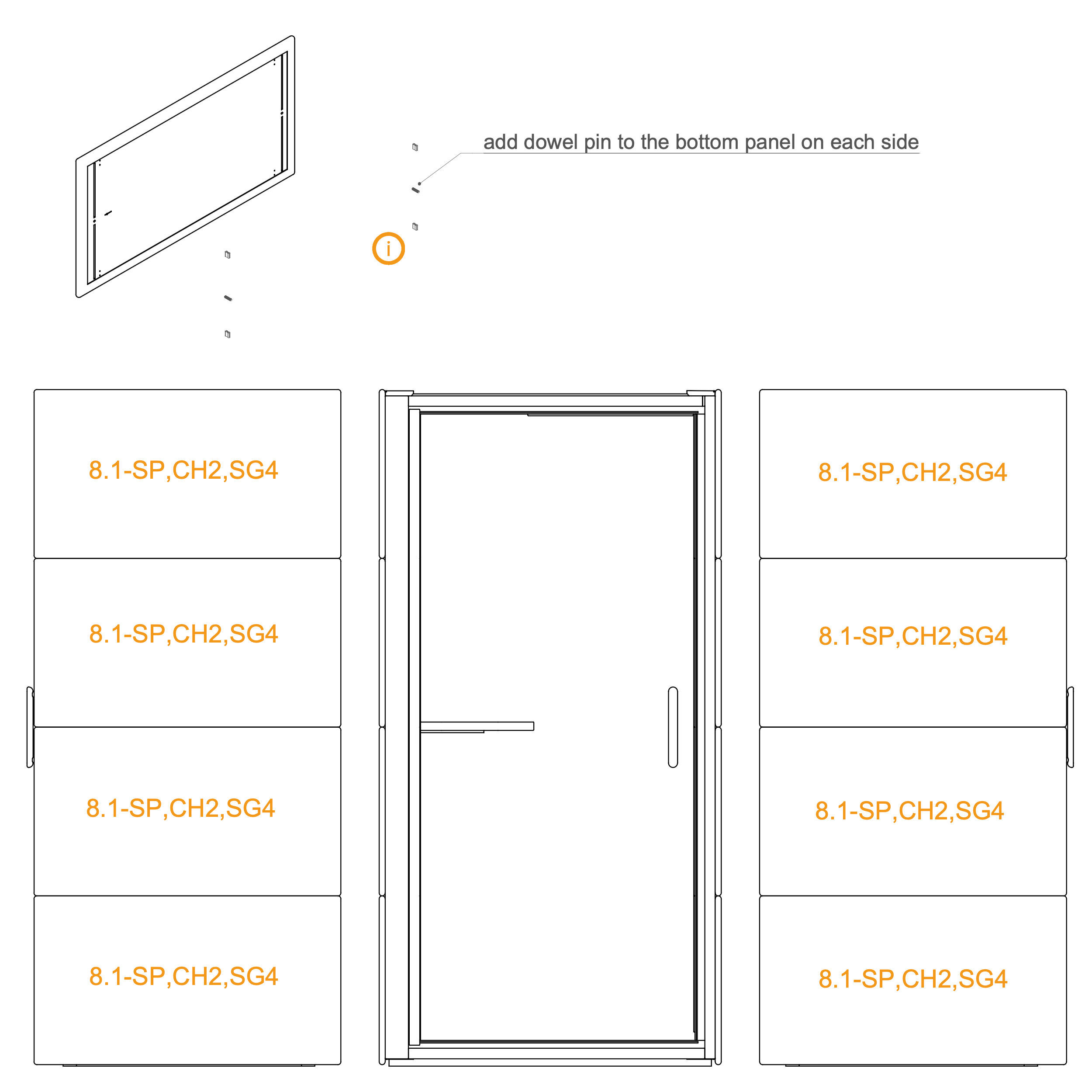
42. Install External panels
Insert pins into the pre‑drilled holes of the bottommost panels.
Install a minimum of four clip connectors into the external panel.
Fit the adjacent panels as shown in the illustration. Begin installation from the bottom and move upward sequentially.
Parts used:
external panel | 8.1-SP_CH2_SG4 | 8×
clip connector | T0122 | 32×
dowel pin | T0122 | 4x
Roof Cover
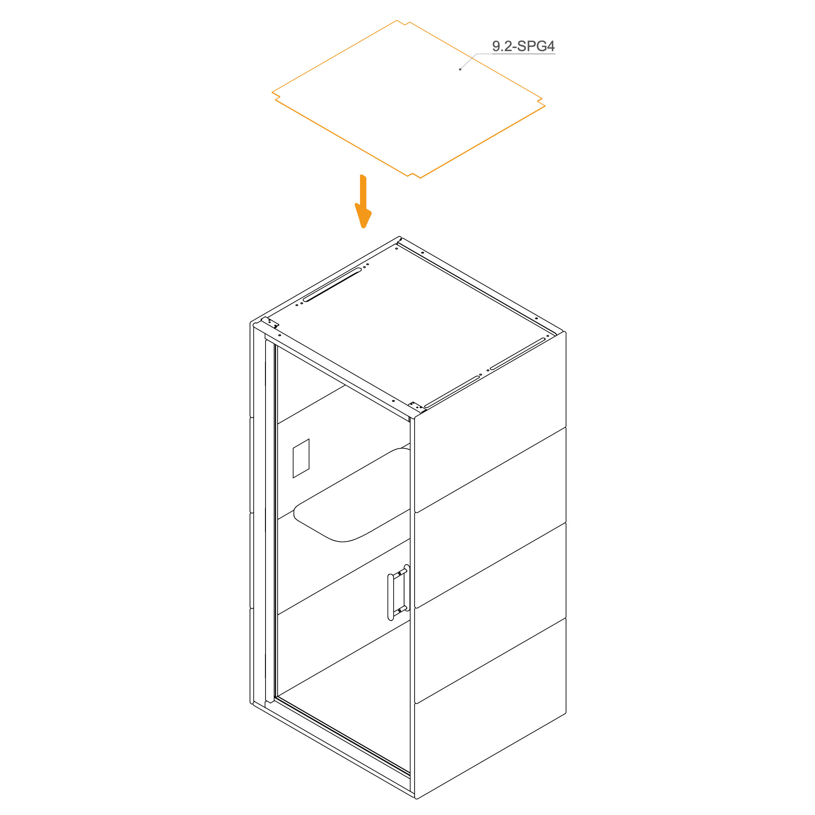
43. Install Roof Cover (Optional)
Place the roof cover on the top of the pod.
Parts used:
Roof cover panel | 9.2-SPG4 | 1×
Door
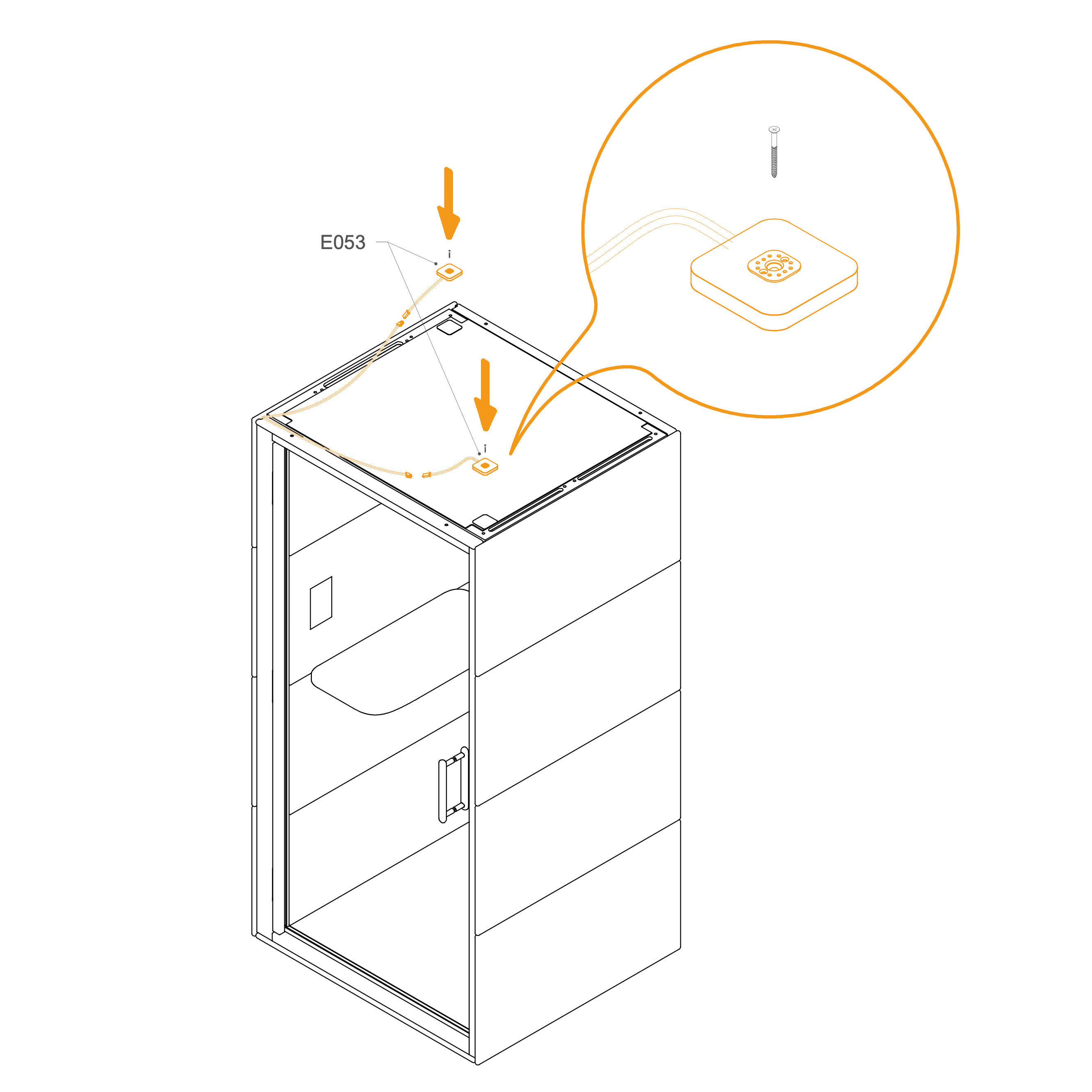
44. Install Occupancy Light
Route the GEN4_ELEKTRO_CABLE OCCUPANCY SIGNALIZATION 4600 mm (E0816) as shown.
Connect the cable to the occupancy light.
Secure the occupancy light (E053) to the frame with the provided screws.
Parts used:
occupancy light | E053 | 2×
3×30 mm screw | T0136 | 2×
45. Door adjustment
Check the door adjustment in the video
46. Install Hinge Cover
Place the hinge covers over the hinges on the door frame as shown.
Secure each cover with screws
Parts used:
hinge cover | not labeled | 6×
M4×10 mm screw | T0310 | 12×
Interior Ledge
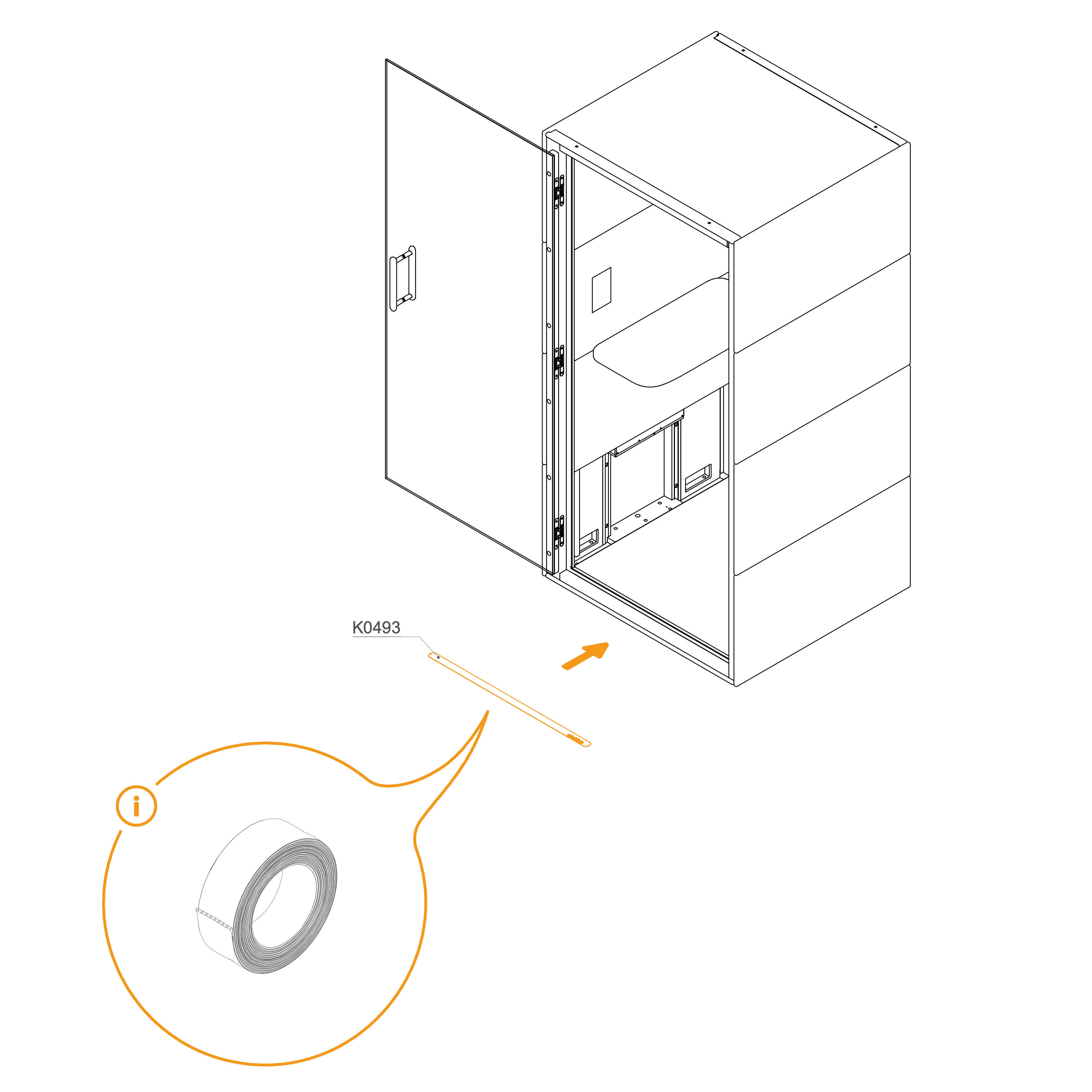
47. Install Ledge
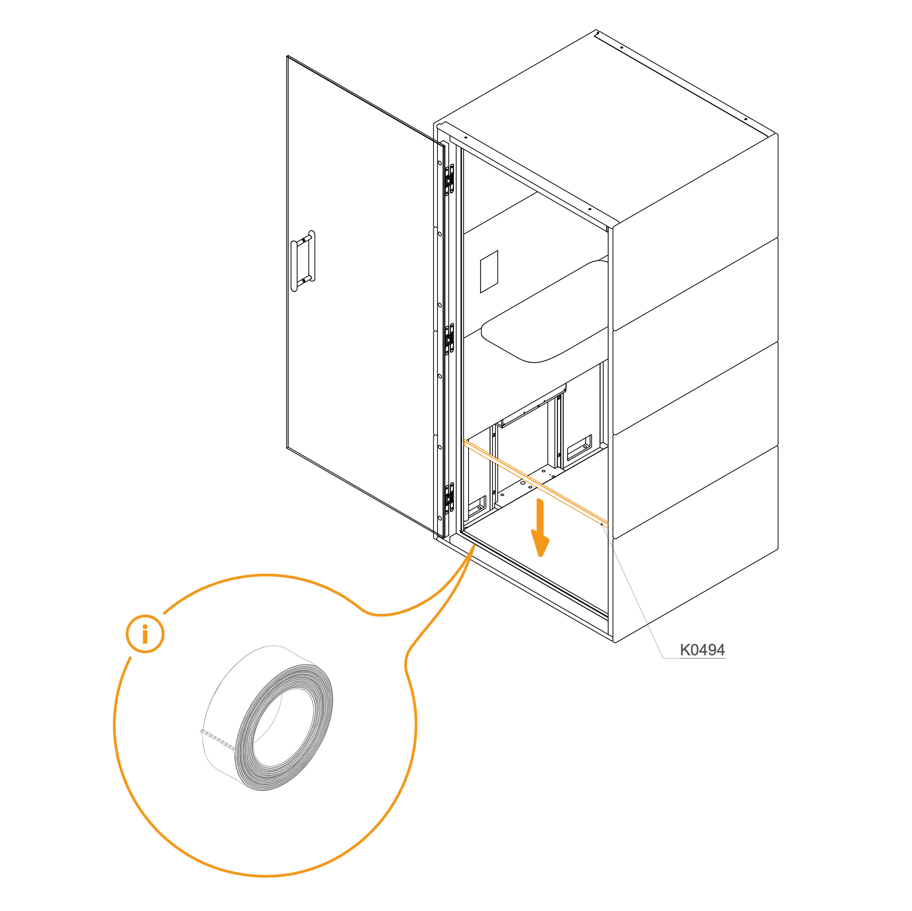
Apply double-sided tape along the back of the ledge (K0493).
Stick the ledge to the indicated position on the frame.
Parts used:
ledge | K0493 | 1×
double-sided tape | 1x
Side Ledge
48. Install Ledge
Apply double-sided tape along the back of the ledge (K0493).
Stick the ledge to the indicated position on the frame.
Parts used:
ledge | K0493 | 1×
double-sided tape | 1x
Cord Connection
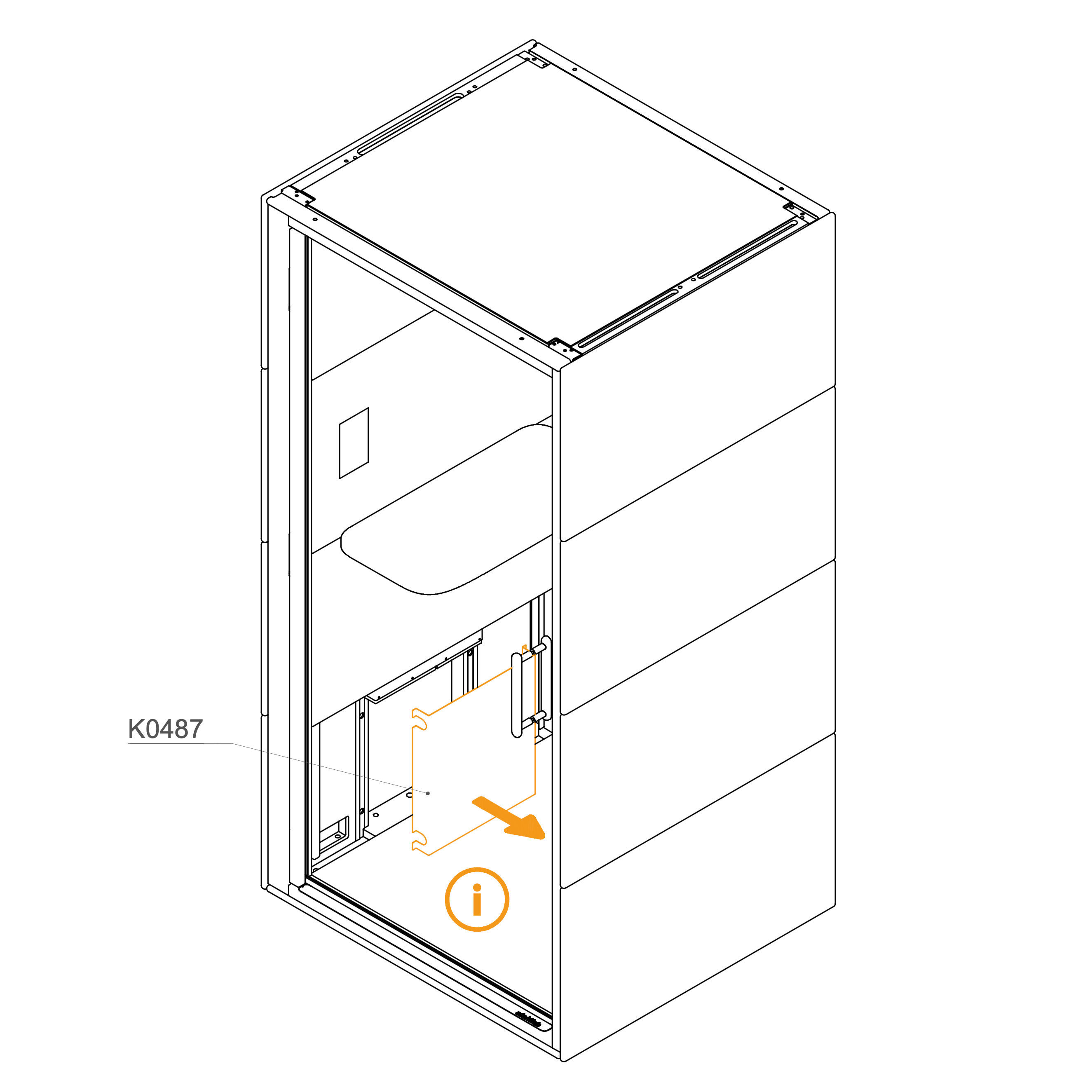
49. Uninstall the cord cover
Remove the Revision Doors (K0487) from the dock.
Parts used:
Revision door | K0487 | 1×
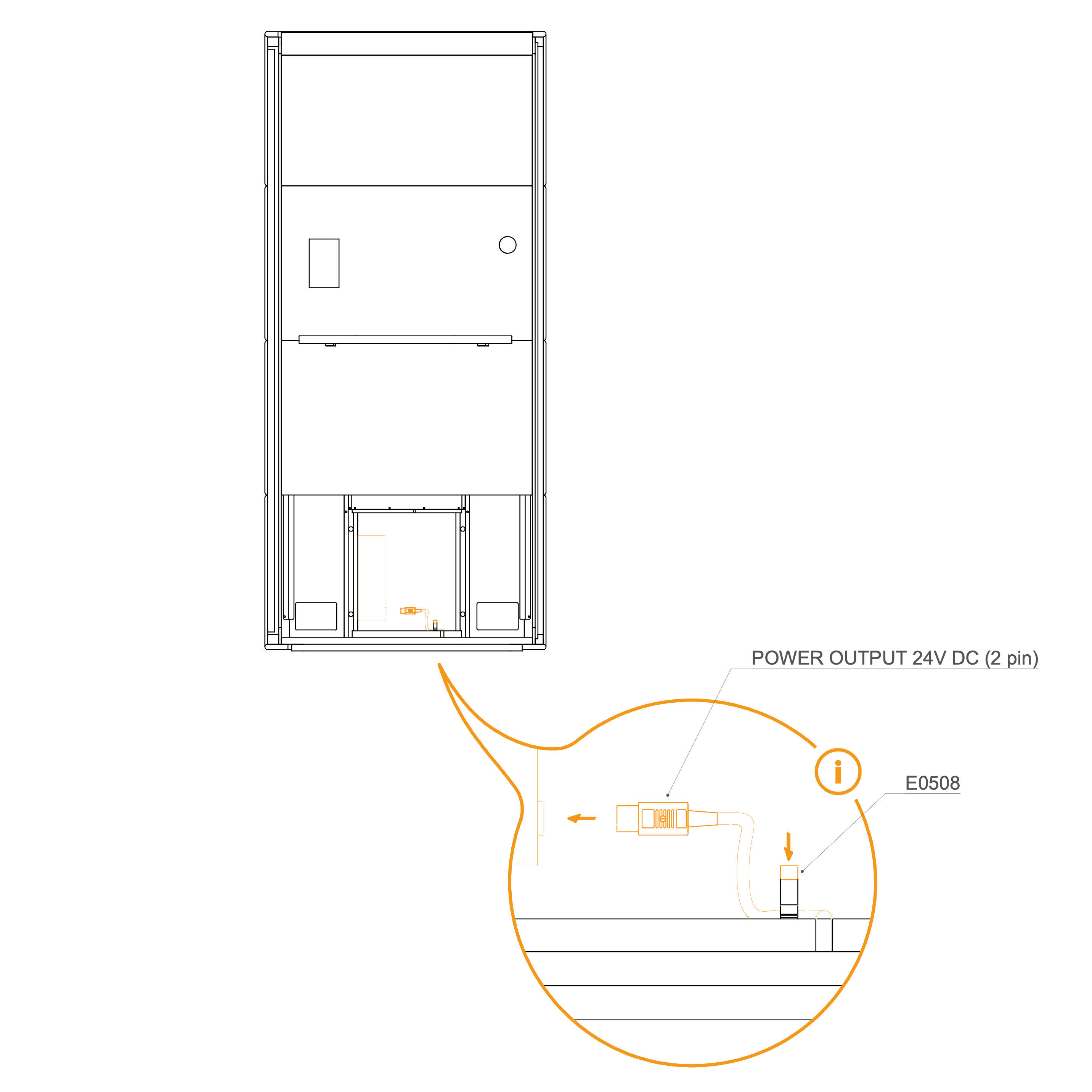
50. Connect the Power Supply Cord to Powerbox
Plug the power cord into the powerbox as shown in the detail view.
Secure the power cord cable by clipping the strain relief (E0508).
Parts used:
strain relief | E0508 | 1×
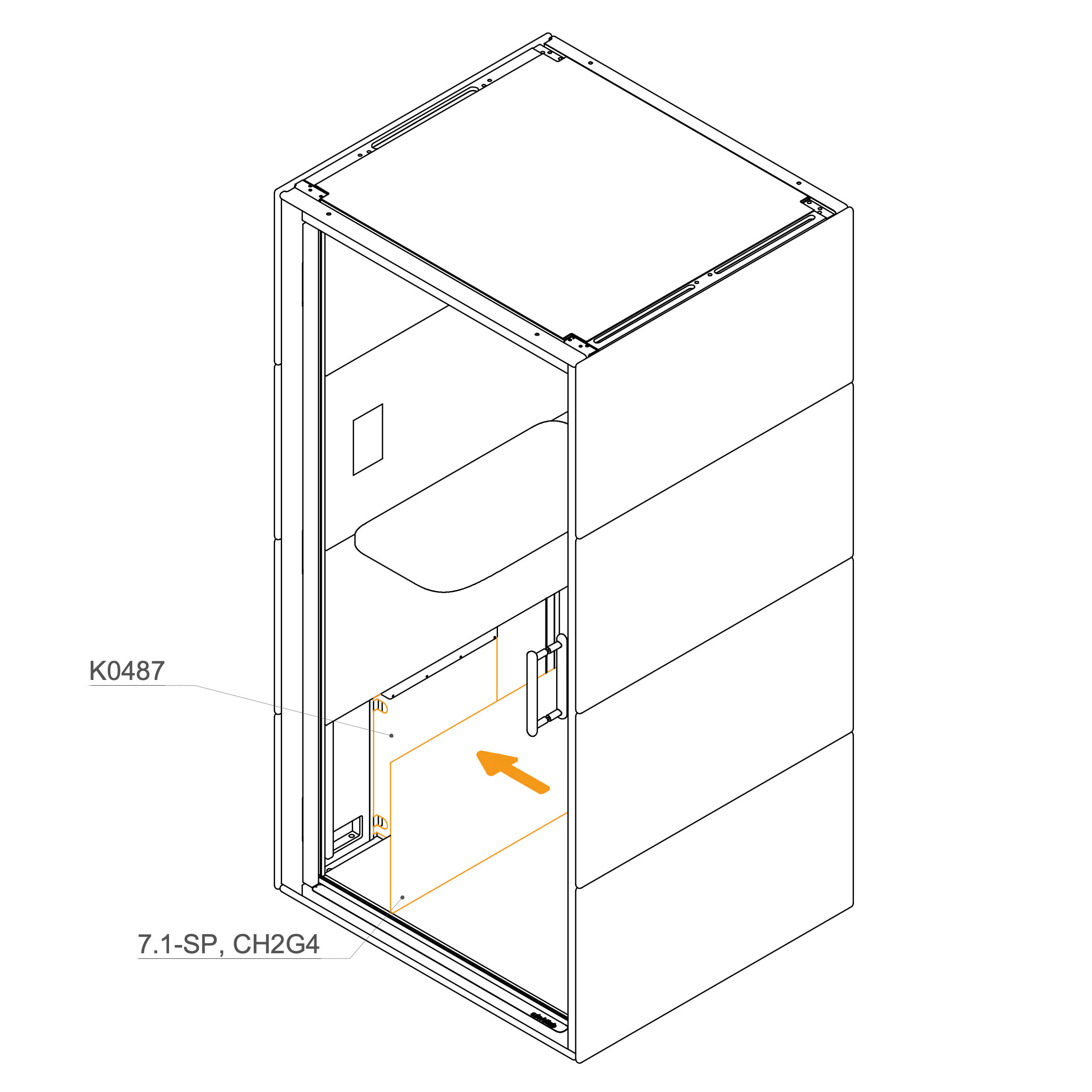
51. Attach the Lower Interior Panel to the Dock
Place the internal panel (7.1-SP, CH2G4) over the power cord section and secure in position.
Parts used:
Internal panel | 7.1-SP, CH2G4 | 1×
Initial Setup
52. Initial Setup
Following assembly, authorized personnel must perform a mandatory initial setup for all GEN4 products. This involves accessing the display settings to configure key parameters, such as the pod model, language, and time synchronization, to ensure all components function correctly.