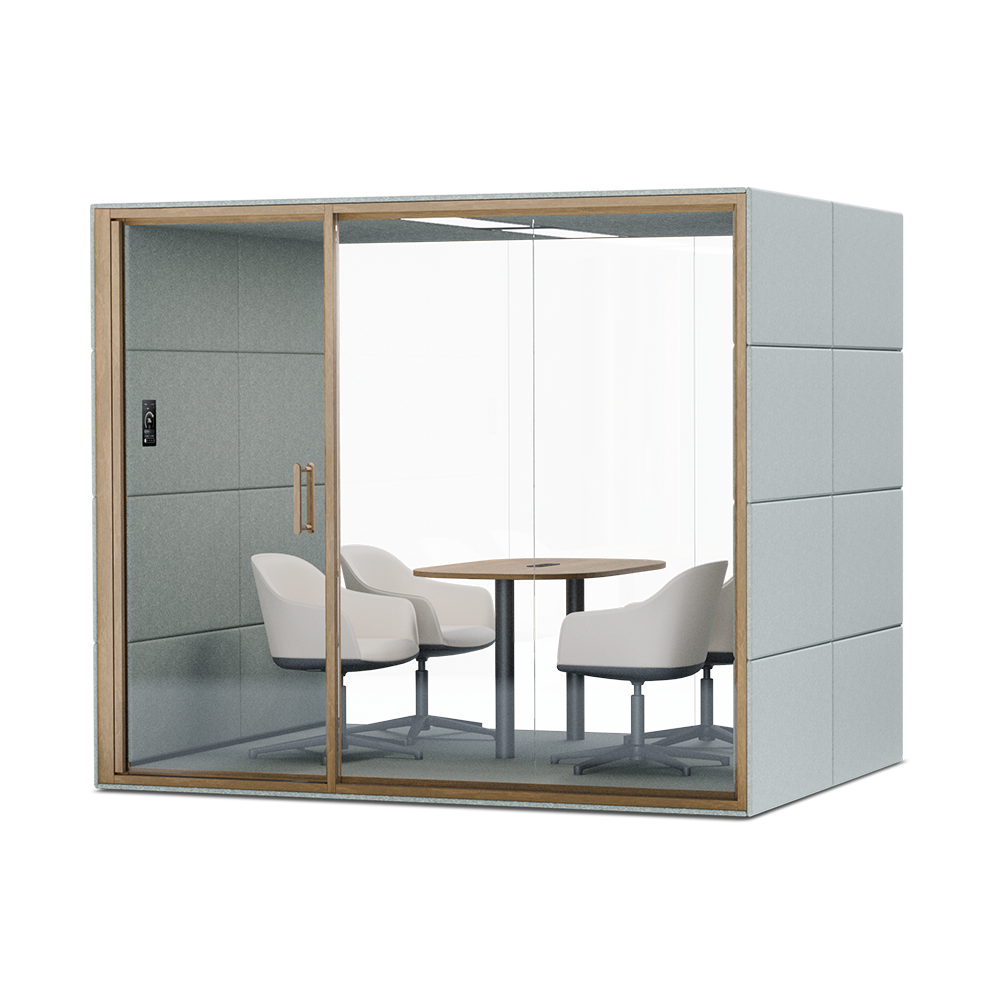
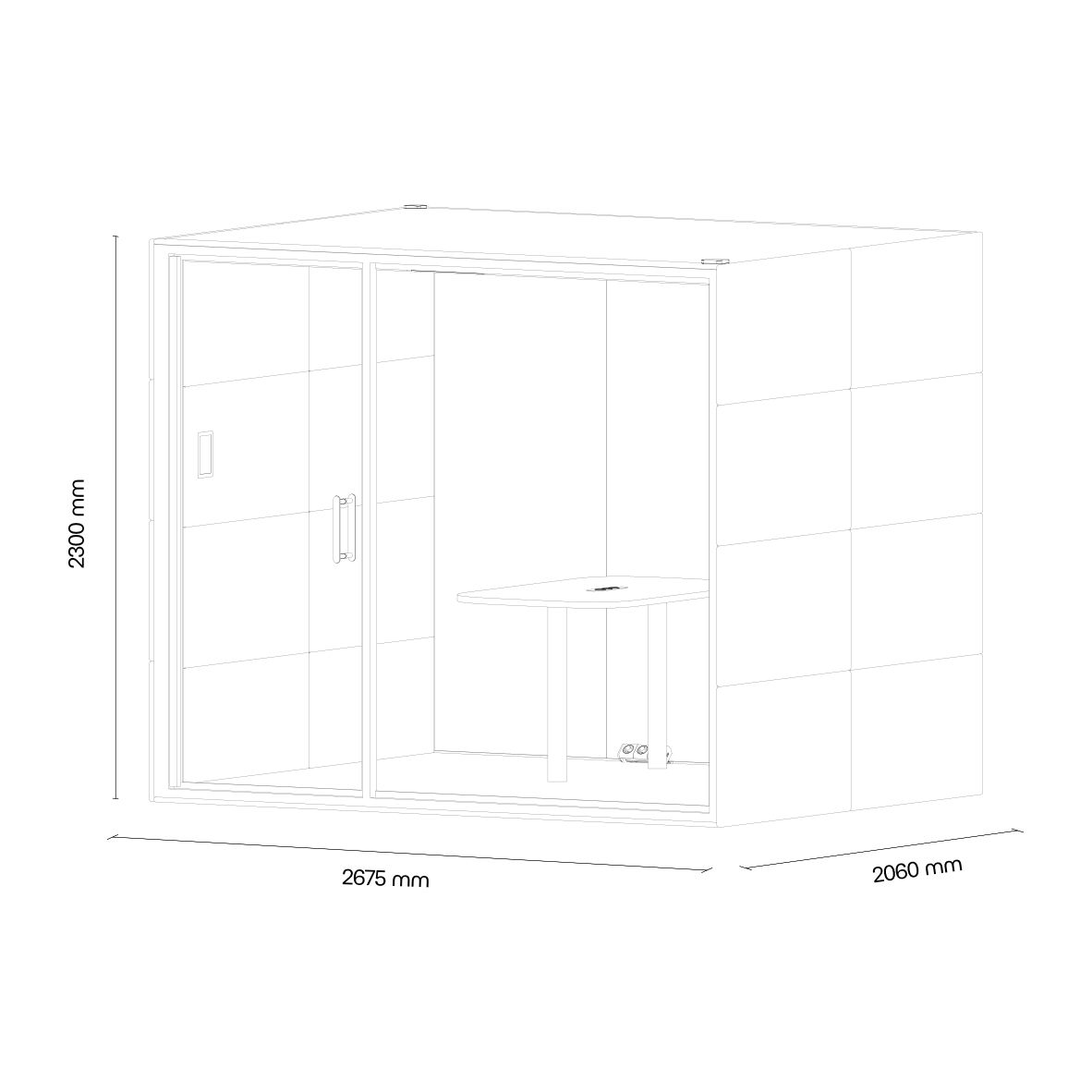
 Instructions by silent lab SUMMIT⁴ Assembly Manual Step-by-step instructions for assembling the SUMMIT⁴ pod for mid-sized meetings by SilentLab. -
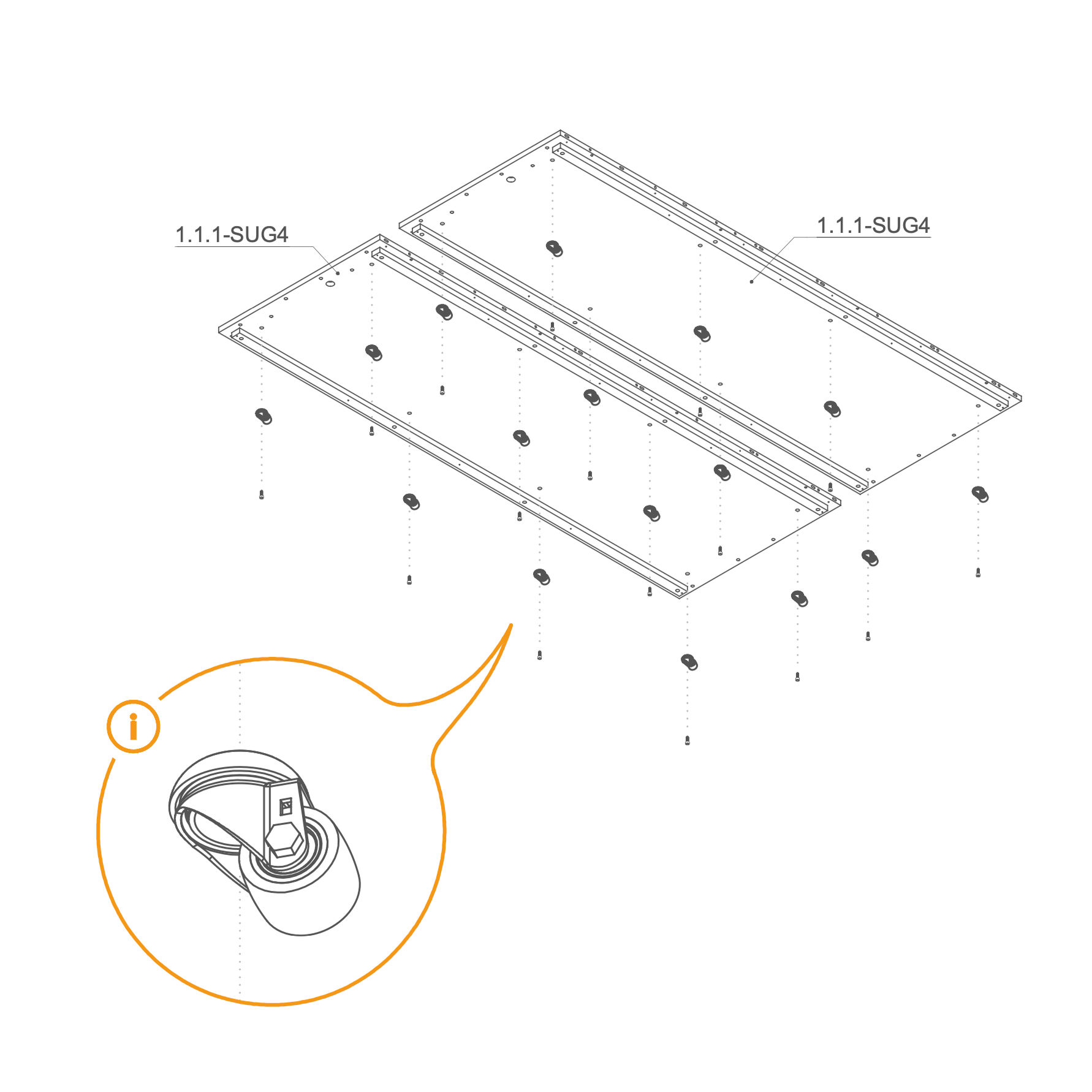
Floor 1. Secure Casters to Floor
- Place floor panels 1.1.1-SUG4 on a flat surface.
- Use the marked holes in the picture to insert the screws (T0509). If your order includes wheels (V0181), attach them to the same holes using screws M10×25 mm (T0509).
Parts used:
- wheel | V0181 | 16×
- M10×25 mm screw | T0509 | 16×
-
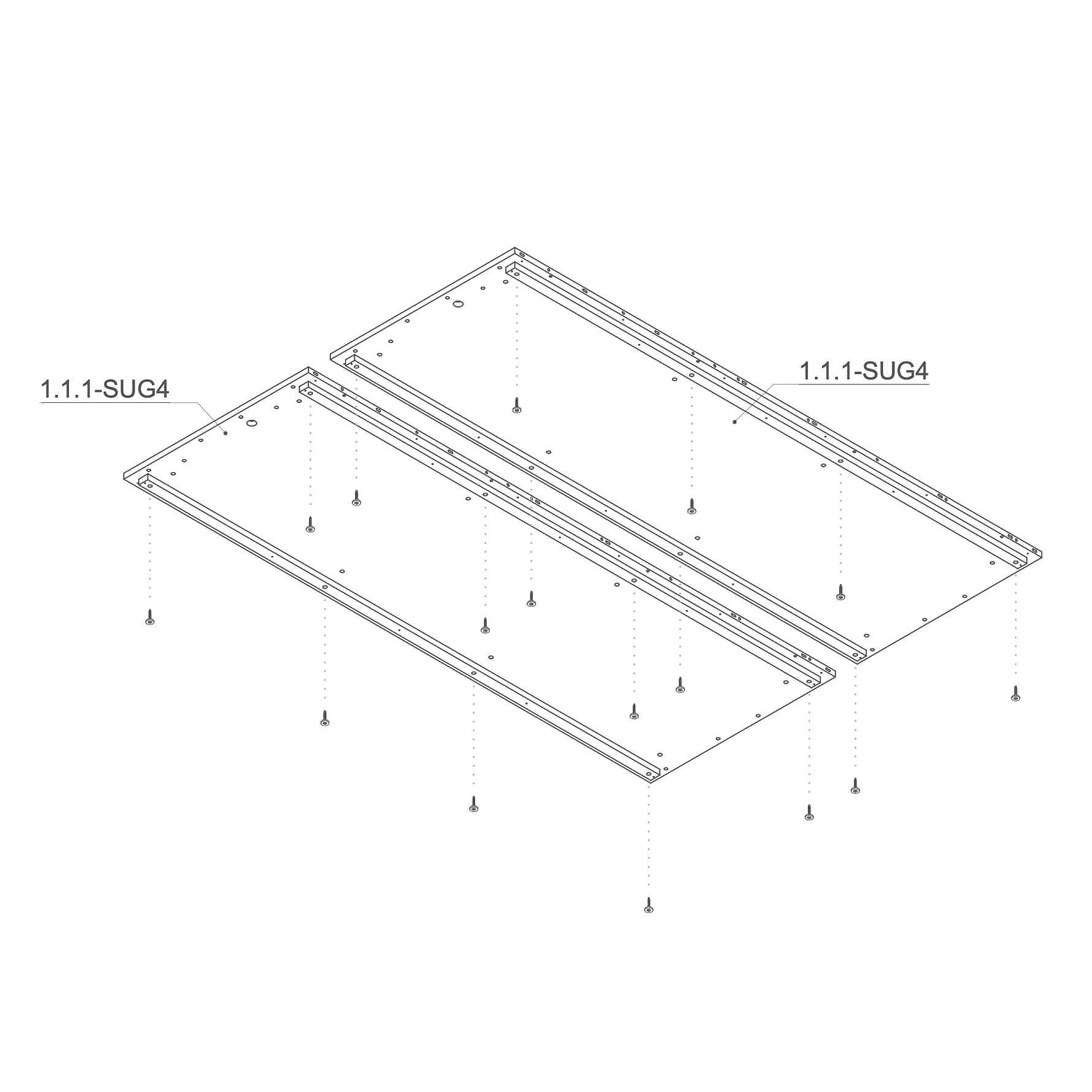
2. Install Leveling Feet
-
Keep the 1.1.1-SUG4 floor panels flipped upside down (bottom side up).
-
Insert one levelling foot (V0050) into each of the 16 marked holes on the underside of the floor panels.
-
Using a Phillips head screwdriver, partially screw in the standing feet. Leave approximately 20 mm of clearance to allow for future adjustments—do not fully tighten them at this stage.
Parts used:
- adjustable foot M10×55 mm | V0050 | 16×
-
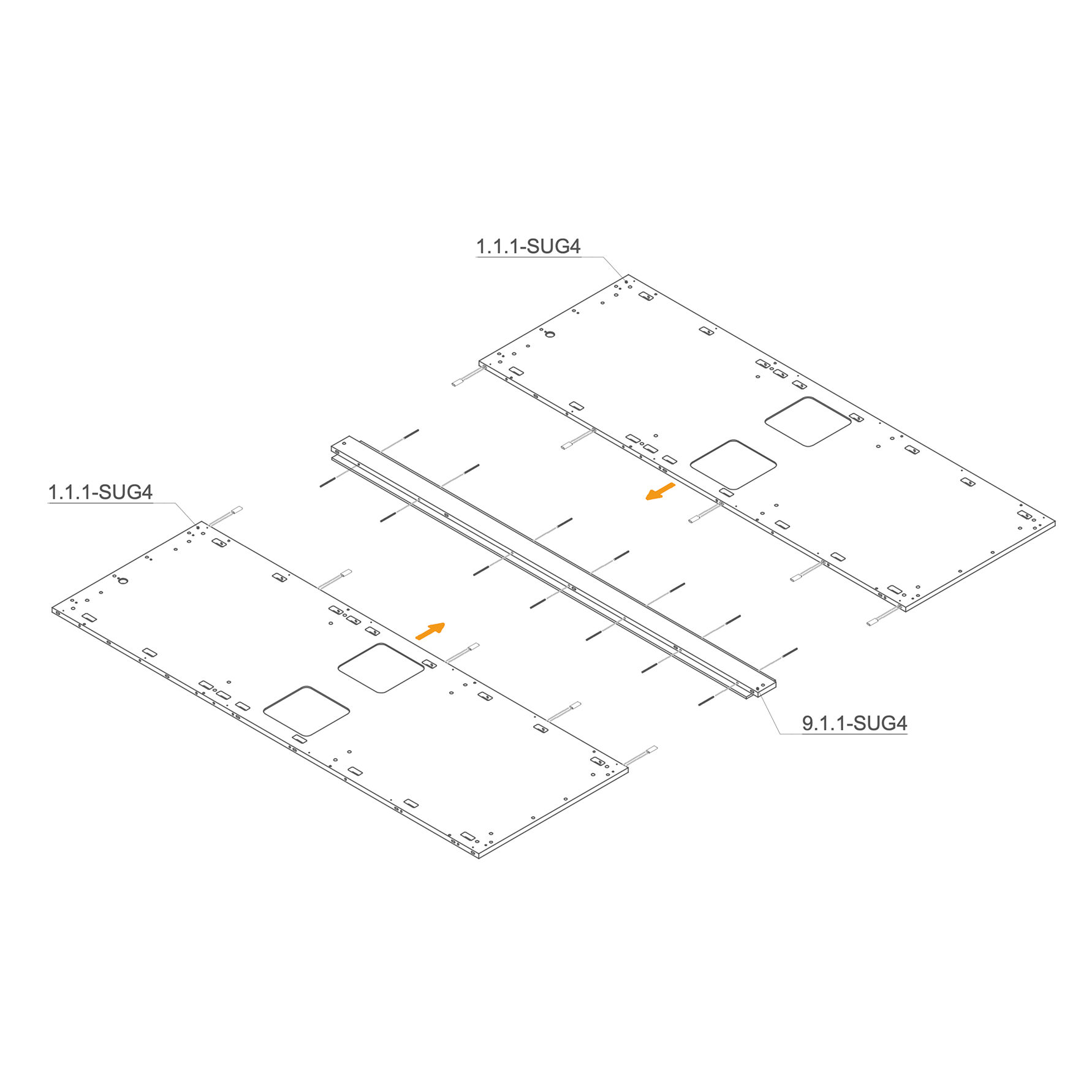
3. Join Floor Panels with Central Connector
-
Lay both floor panels (1.1.1-SUG4) on the ground.
-
Insert D8×50×22 mm dowels (T0536) into the designated oval holes for alignment and reinforcement.
-
Insert the M6x90 mm threaded rod (T0547) by screwing it into the central profile's nuts. Then, seat the rod into the floor panel's mounting slots.
-
Position the central joining profile (9.1.1-SUG4) between the two floor panels and press them firmly together.
Parts used:
-
4. Secure Central Profile to Floor Panels
- Ensure the two floor panels are correctly aligned and the central joining profile is fully seated.
- Insert the M4×25 mm screws (T0435) into the remaining pre-drilled holes along the central seam.
- Tighten all 12 screws using a screwdriver or Torx bit, securing the floor panels to the central profile.
Parts used:
- M4×25 mm screw | T0435 | 12×
-
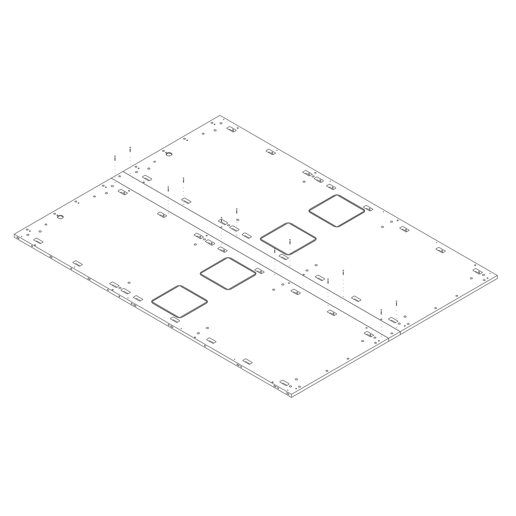
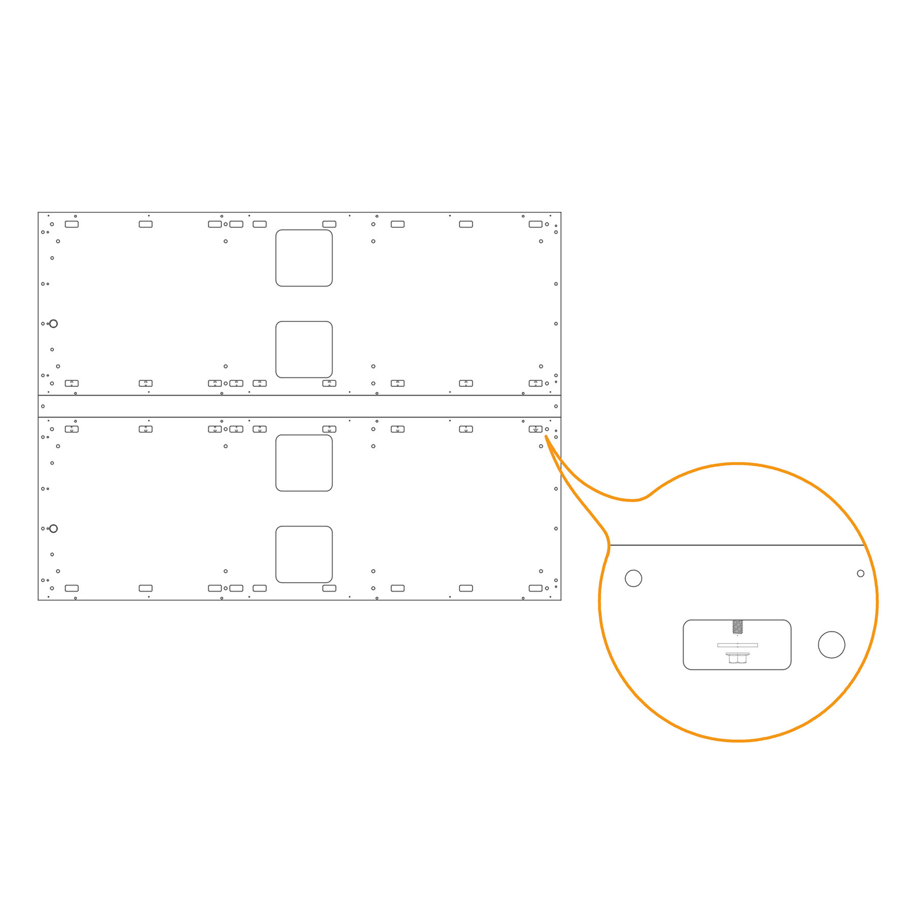
5. Secure Mounting Points with Flange Nuts
-
Locate the 14 mounting slots on the floor assembly, as shown in the zoomed detail.
-
Insert one M6 washer (T0198) into each threaded rod within the slot.
-
Place one M6 flange nut (T0514) onto each threaded rod.
-
Firmly tighten using a ratchet wrench.
Parts used:
-
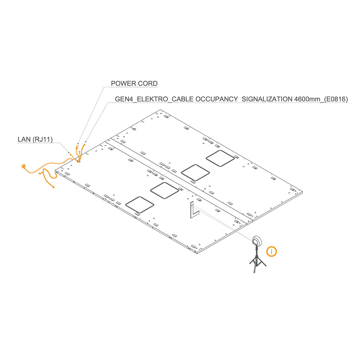
6. Route Cables Through the Hole
-
Lay the GEN4_ELEKTRO_CABLE OCCUPANCY SIGNALIZATION 4600 mm (E0816), LAN cable (RJ45), and power cord through the hole in the floor panel. Follow the marked path shown in the bottom view, ensuring the cables are not pinched.
-
Use a laser level and L-angle (or a spirit level) to level the floor. Adjust the height of the standing feet using a Philips head bit.
-
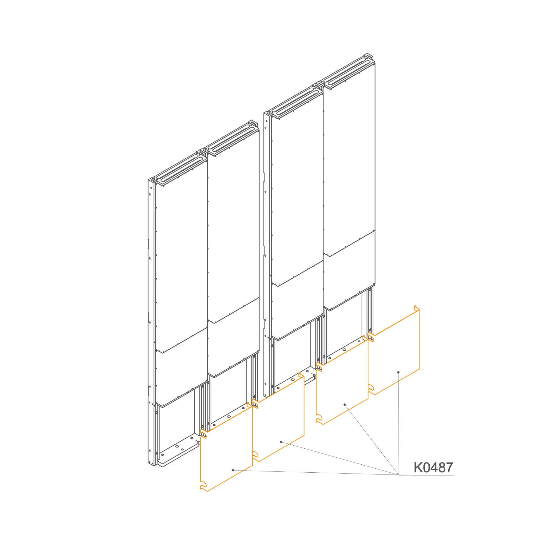
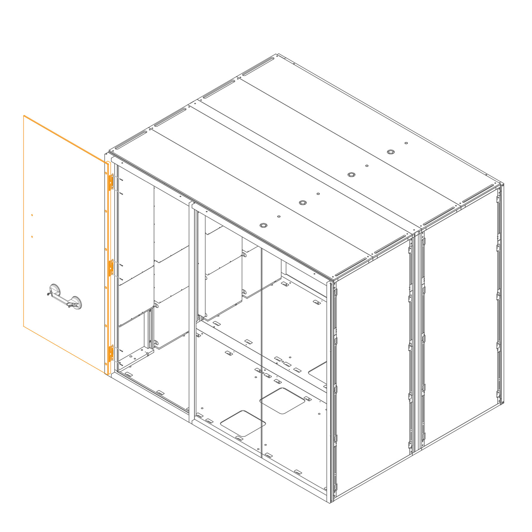
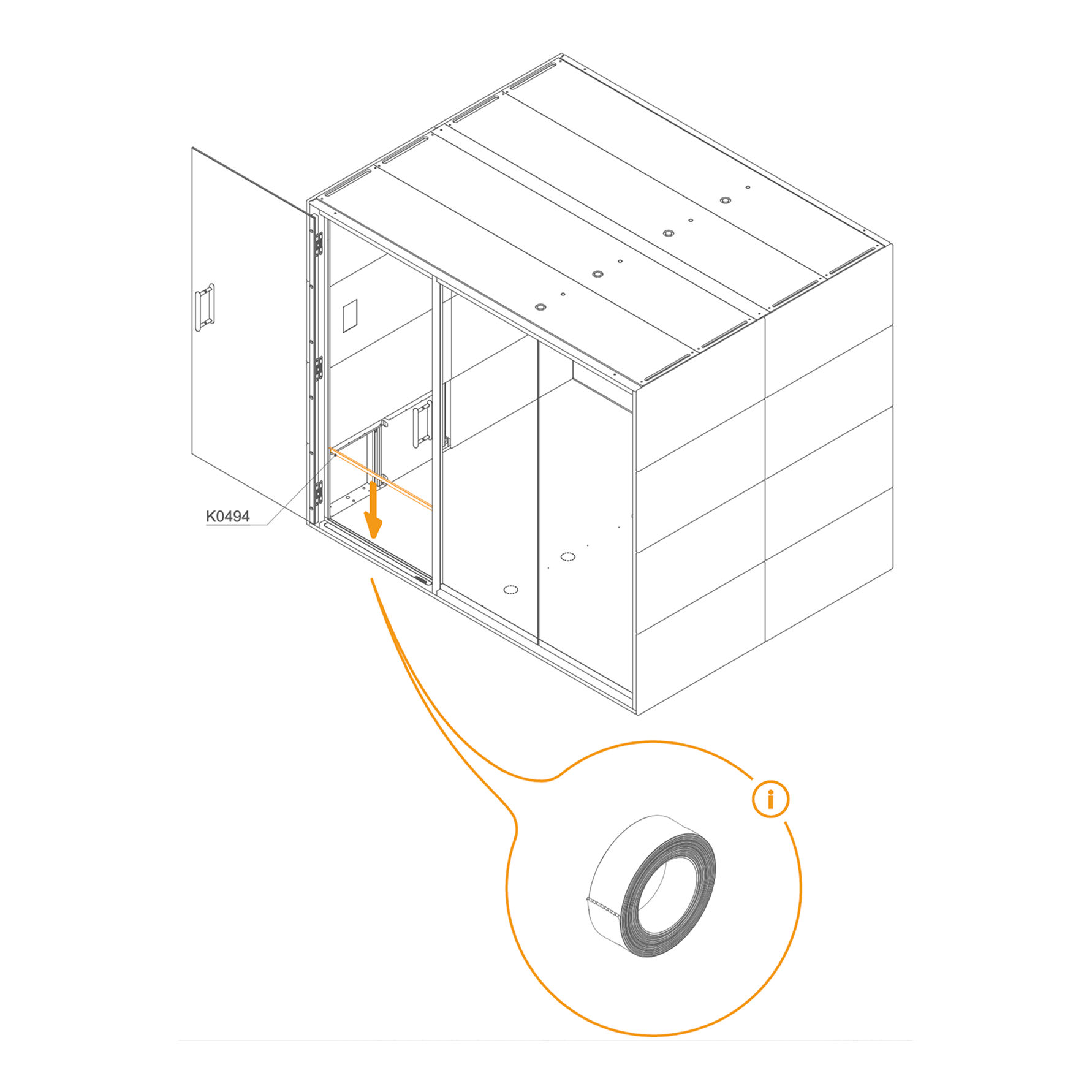
Dock 7. Remove Revision Doors
- Remove the Revision Doors (K0487) from the docks.
Parts used:
- Revision door | K0487 | 4×
-
8. Mount Dock on the Floor Panel
-
Route the cables (power and RJ11) through the dedicated channel on the leftmost frame.
-
Position one dock at a time in place.
-
Insert dowels into the predrilled holes on the top of the docks to maintain proper alignment.
Parts used:
- 8×30 mm dowel pin | T0122 | 13×
-
9. Secure the Dock to the Floor Panel
-
Insert M8×45 mm hex‑head bolts (T0204) through the inner mounting holes.
-
Place a washer (T0198) underneath each bolt head.
-
Tighten securely until the bolt and washer are seated flush with the panel surface.
Parts used:
-
10. Secure the Docks and Connector
-
Insert an M6 × 30 mm bolt (T0511) through the aligned holes on the exterior side of the dock panels. Place a washer (T0198) under the bolt head. Insert the washer onto the opposite cutout and secure it by an M6 flange nut (T0514).
-
Ensure the dock panels and the connector are properly aligned. Tighten the screws securely.
Parts used:
-
6×30 mm bolt | T0511 | 20×
-
Flange nut M6 | T0514 | 10×
-
8.4×24×2.0 mm Washer | T0198 | 30×
-
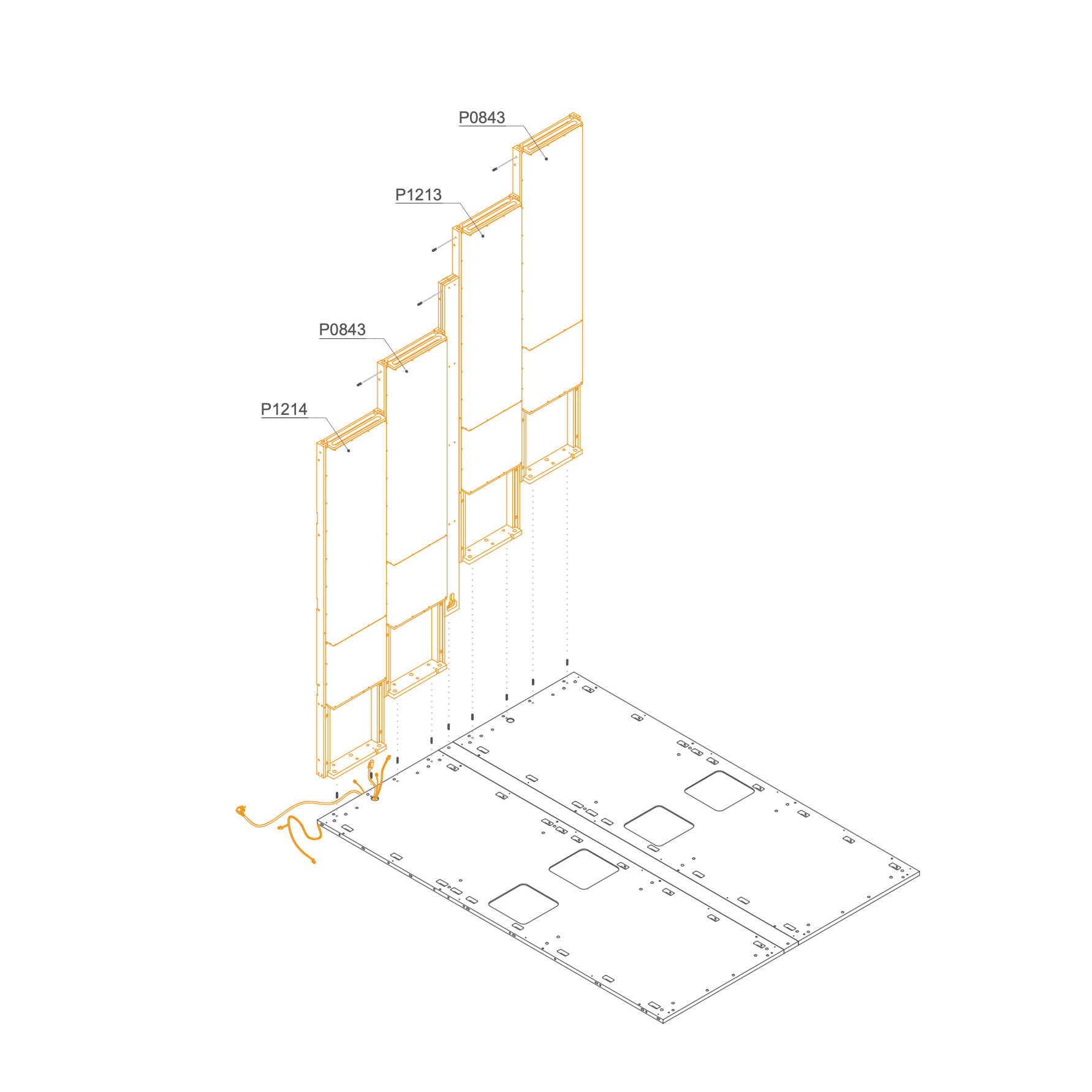
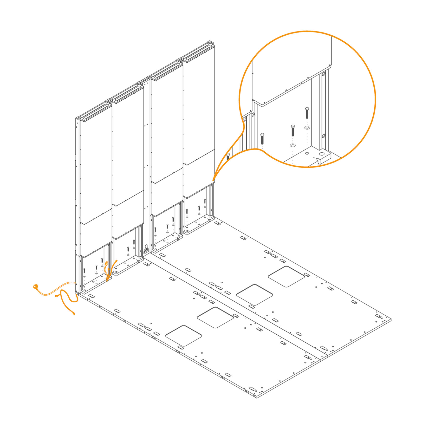
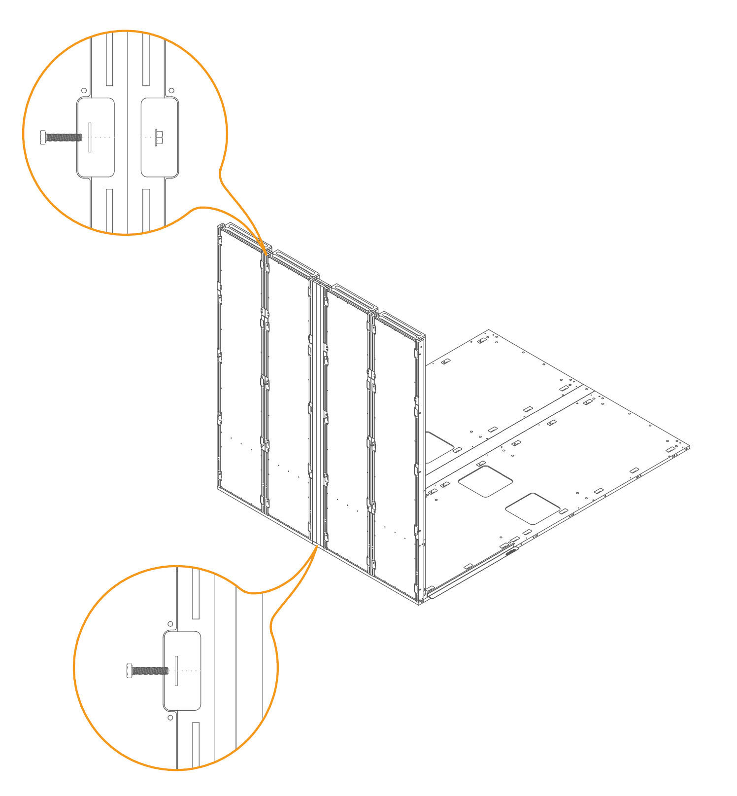
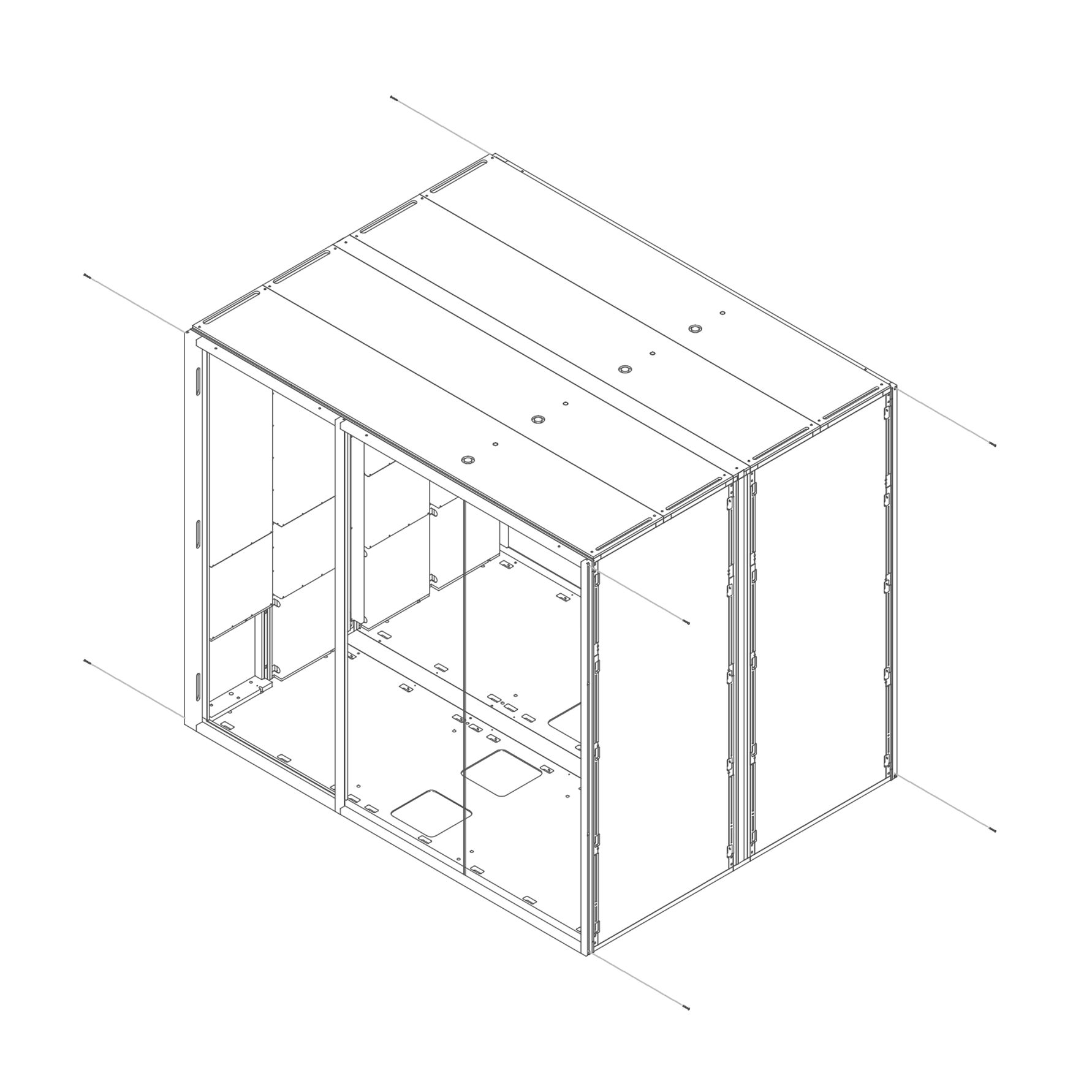
Panel 11. Mount Wall Panels to the Floor
- Insert dowel pins (T0122) into the predrilled holes in the floor panel.
- Align the panel with the pre-drilled holes on the floor panel (1.1.1-SUG4) and the dock frame.
- Secure the bottom of the panels using M8×45 mm hex head bolts (T0204) and washers (T0198) through the mounting points.
Parts used:
-
8×30 mm dowel pin | T0122 | 7×
-
M8×60 mm screw | T0039 | 9×
-
8.4×24×2.0 mm Washer | T0198 | 9×
-
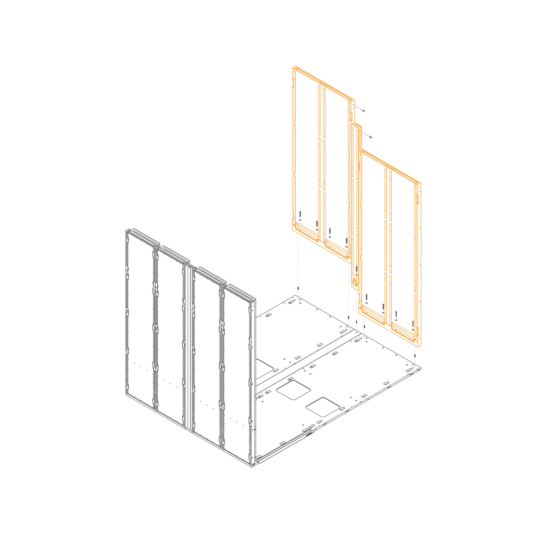
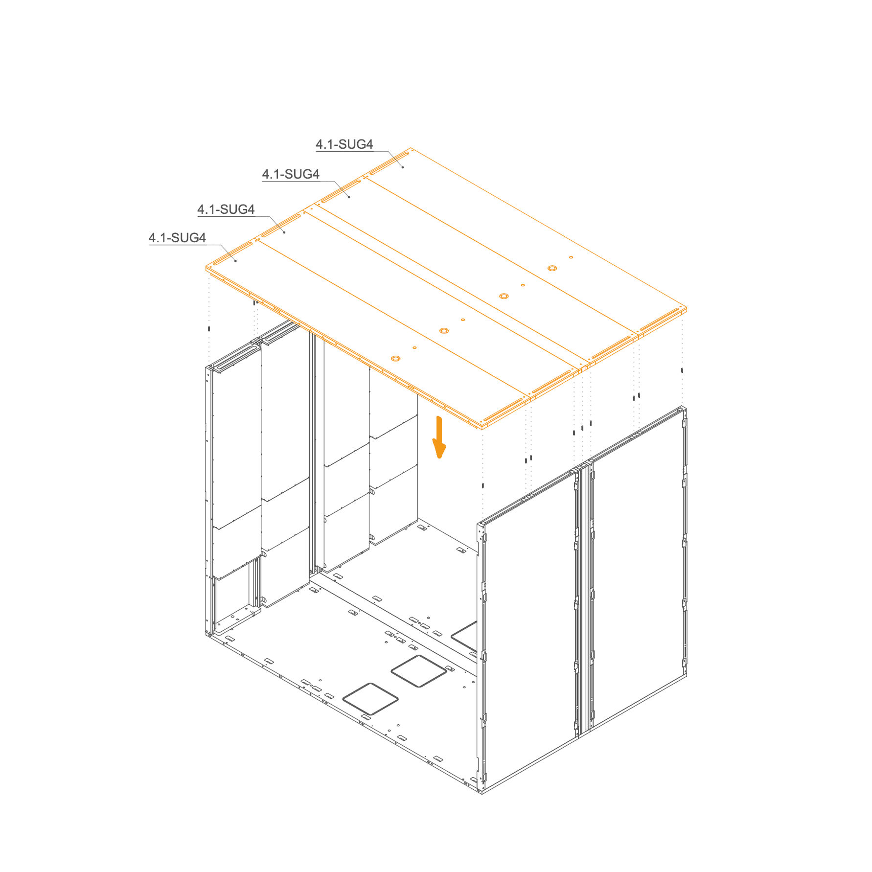
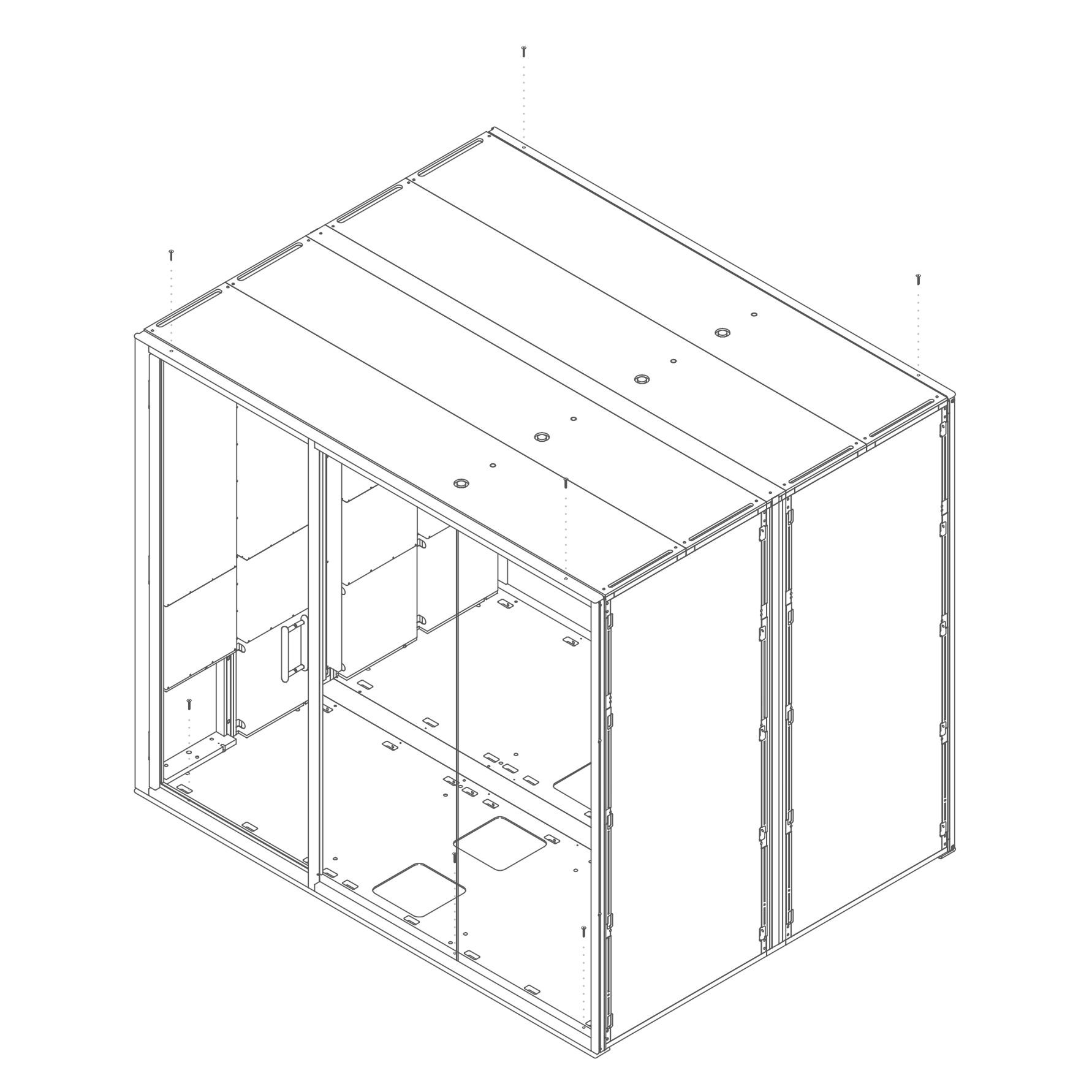
Roof 12. Attach Roof
- Identify part 4.1-SUG4, the roof panel.
- Insert eight dowel pins (T0122) into the designated guide holes along the top edges of the wall panels.
- Carefully lower the roof panel onto the structure, aligning the dowel pins with the corresponding holes on the underside of the roof.
- Ensure the panel sits flush and is properly seated before proceeding to fasten.
Parts used:
- 8×30 mm dowel pin | T0122 | 18×
-
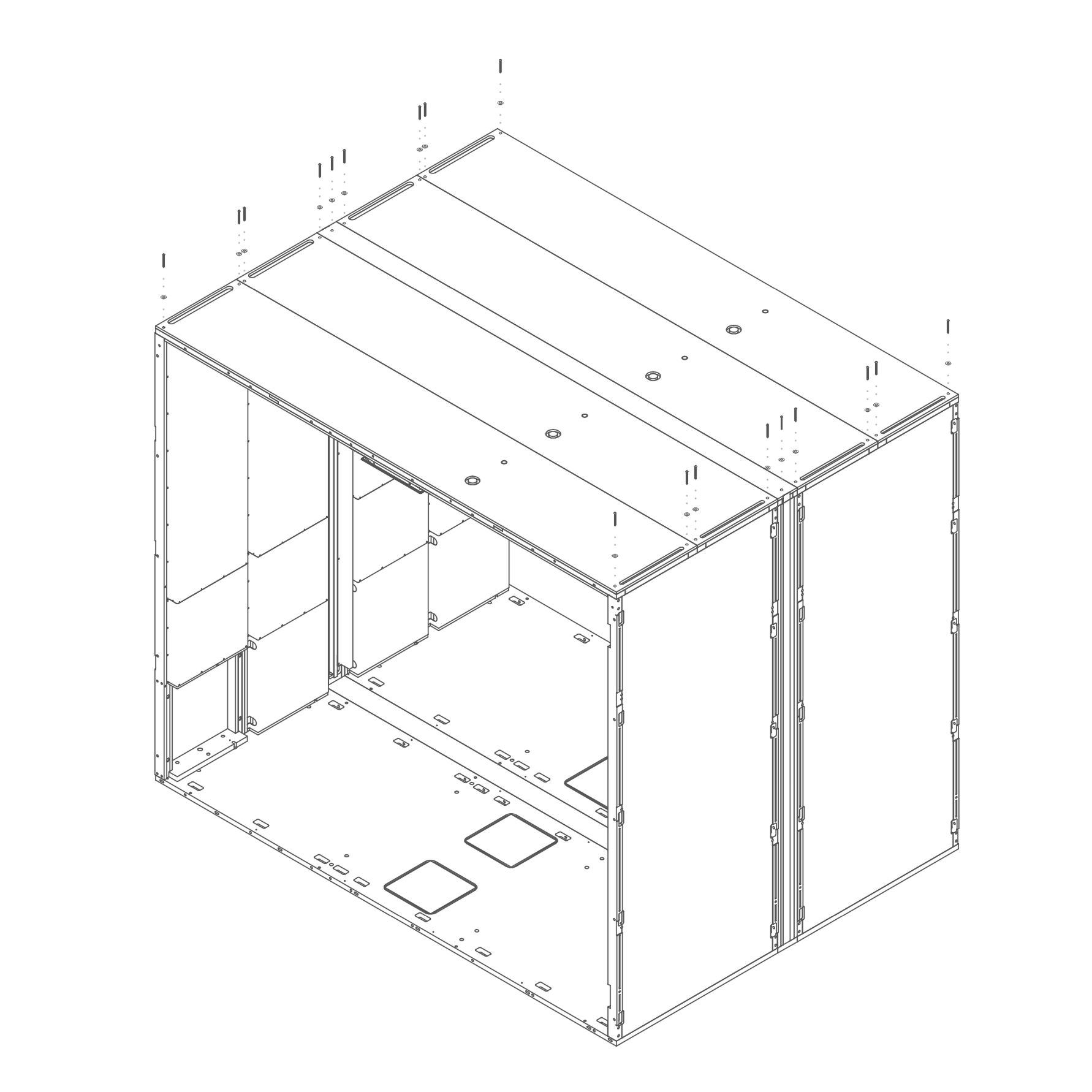
13. Secure Roof
- Insert one M6×60 mm bolt (T0510) through each of the 18 designated holes on the roof.
- Place one 8.4×24×2.0 mm washer (T0198) under each bolt head.
- Tighten all bolts using a hex key or screwdriver until the roof is firmly attached to the wall structure.
Parts used:
-
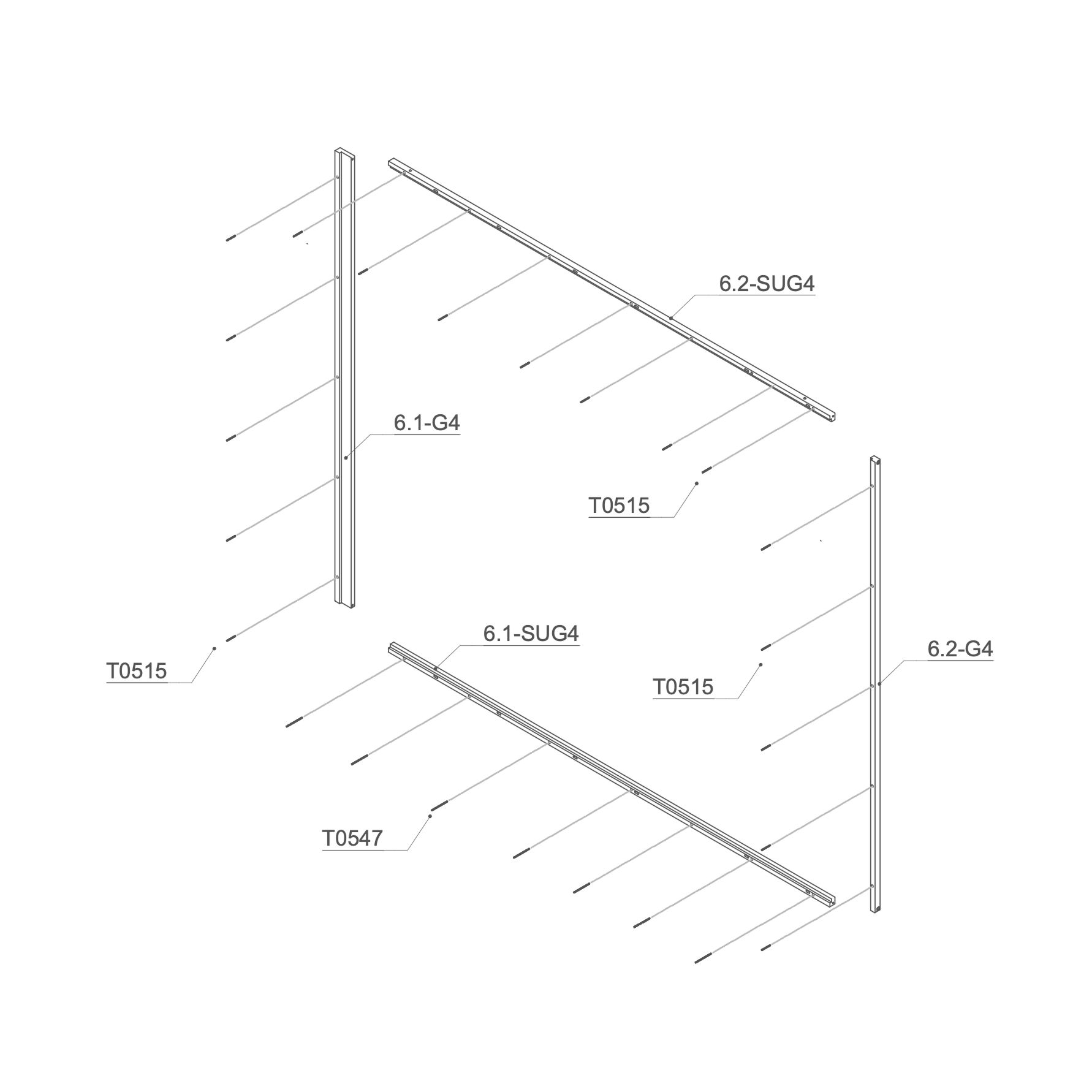
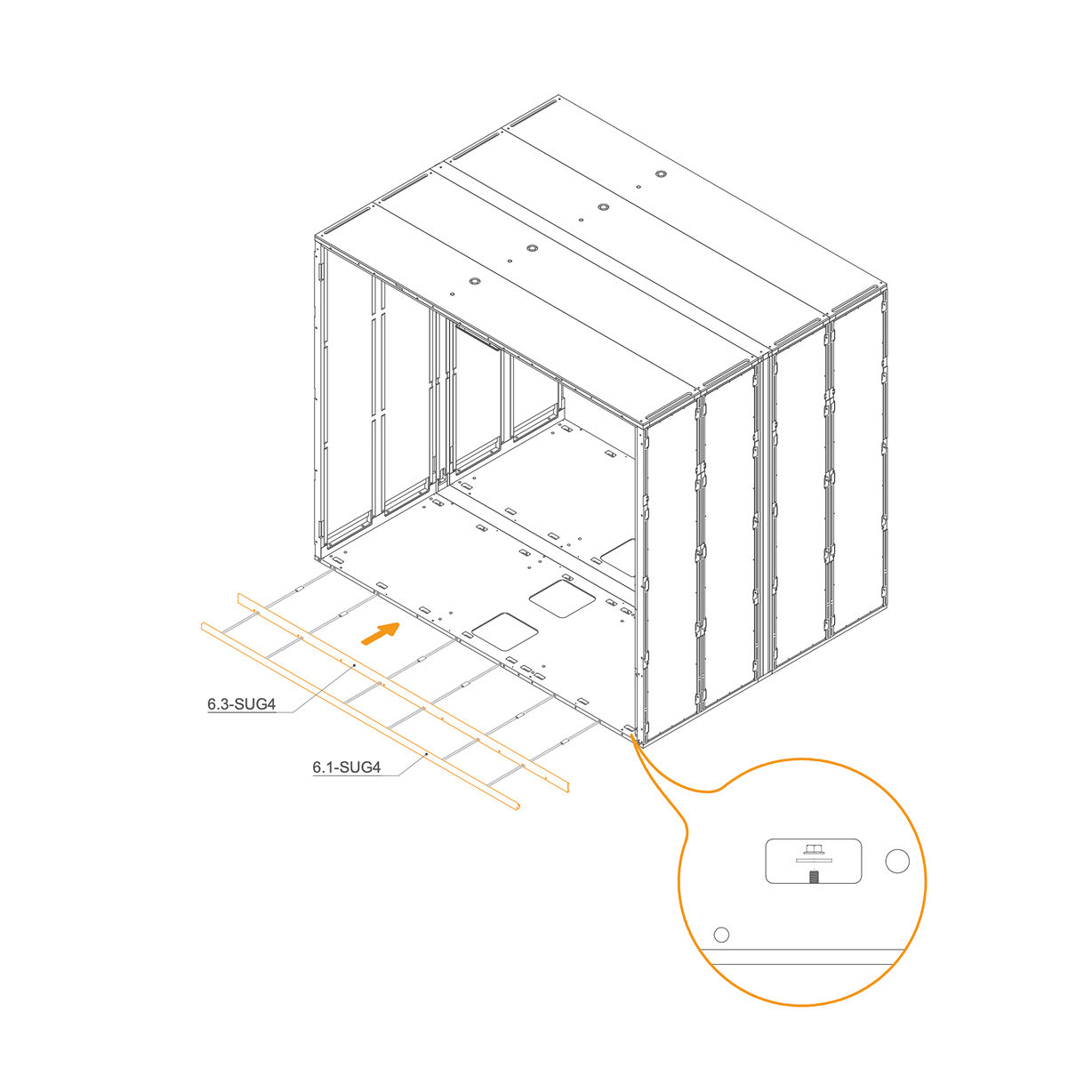
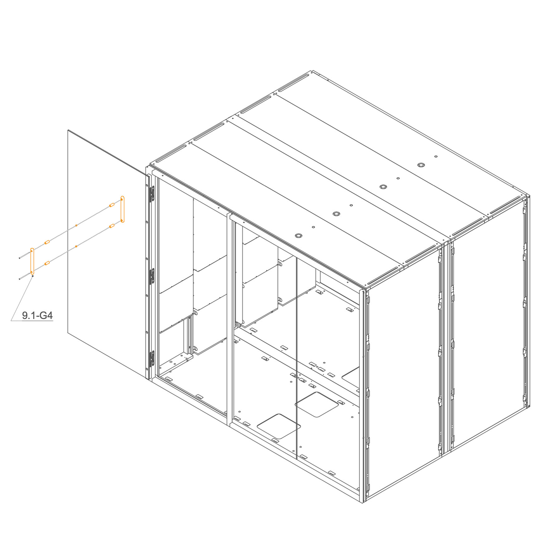
Rear Frame 14. Attach Threaded Rod to Rear Frame
- Place the M6×90 mm threaded rod (T0547) into the 6.1 SUG4 and M6×50 mm threaded rod (T0515) into the 6.1-G4, 6.2-G4 and 6.1-SUG4.
Parts used:
-
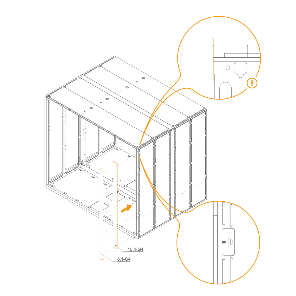
15. Attach Rear Frame to the Pod
- Insert D8×50×22 mm dowels (T0536) into the oval holes
- Align the horizontal frame 6.1-SUG4 and 6.3-SUG4 with the mounting slots at the rear edge of the floor panel.
- Place washers (T0198) and M6 flange nuts (T0514) on the threaded rod in the floor cutouts.
- Ensure the frame is aligned correctly before tightening properly.
Parts used:
-
D8×50×22 mm dowel | T0536 | 6×
-
M6 Flange nut | T0514 | 7×
-
8.4×24×2.0 mm Washer | T0198 | 7×
-
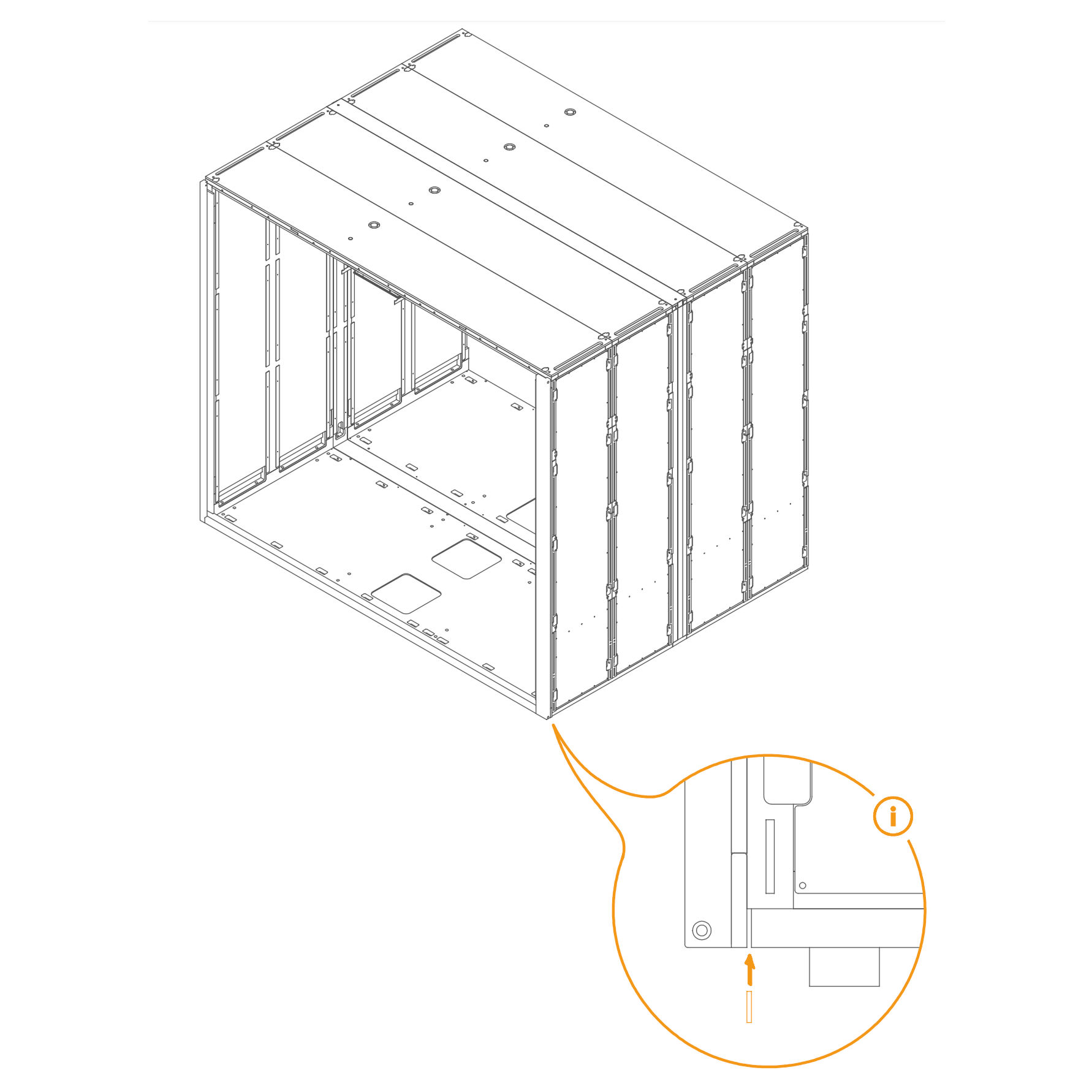
16. Check Gap and Insert Spacer if Necessary
- If there is a gap between the frame and the floor, insert a spacer into the groove.
-
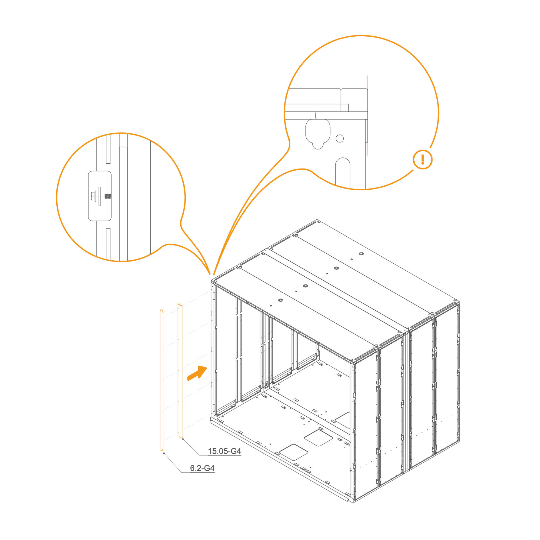
17. Attach Rear Frame to the Wall Panel
-
Place the two vertical frames, 15.05-G4 and 6.2-G4, in their designated positions.
-
Secure each frame by inserting a washer (T0198) and tightening an M6 flange nut (T0514) onto the threaded rod in the slot openings.
-
Ensure the frames are properly aligned before fully tightening the nuts.
Parts used:
-
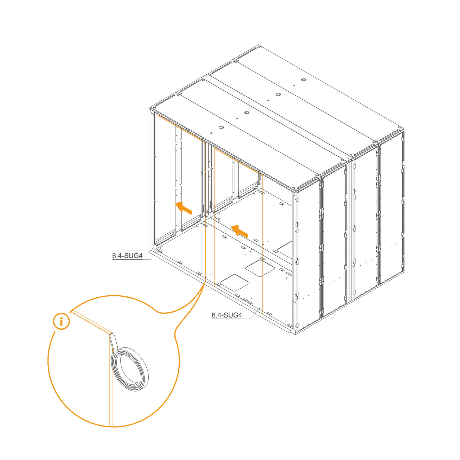
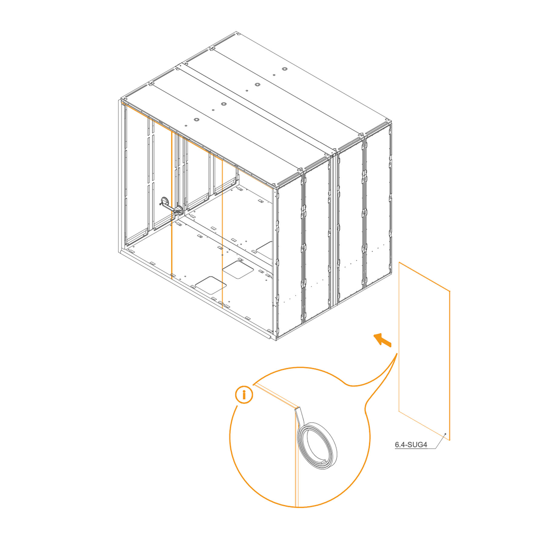
18. Install Rear Glass into the Frame
-
Clean the edge of the glass with the glass cleaner to remove any dust or grease.
-
Carefully apply double-sided gel tape along the cleaned edge. Do not remove the protective foil from the tape at this stage.
-
Insert the glass (6.4-SUG4) into the groove in the Rear frame.
-
Use suction cups to secure the second glass.
Parts used:
-
19. Install Rear Glass into the Frame
-
Clean the edge of the glass with the glass cleaner to remove any dust or grease.
-
Carefully apply double-sided gel tape along the cleaned edge. Do not remove the protective foil from the tape at this stage.
-
Insert the glasses (6.4-SUG4) into the groove in the Rear frame.
Parts used:
-
20. Secure Glass Panels with Double-sided Tape
- Align the glass with the groove on the side of the panel. Remove the protective film from the double-sided tape and use suction cups to pull the glass together.
-
21. Attach Rear Frame to the Dock
- Locate part 15.04-G4 (front right vertical profile) and 6.1-G4 (front left vertical profile).
- Align each profile with the corresponding front frame posts.
- Secure Rear frame using M6 flange nuts (T0514) and washers (T0198).
Parts used:
-
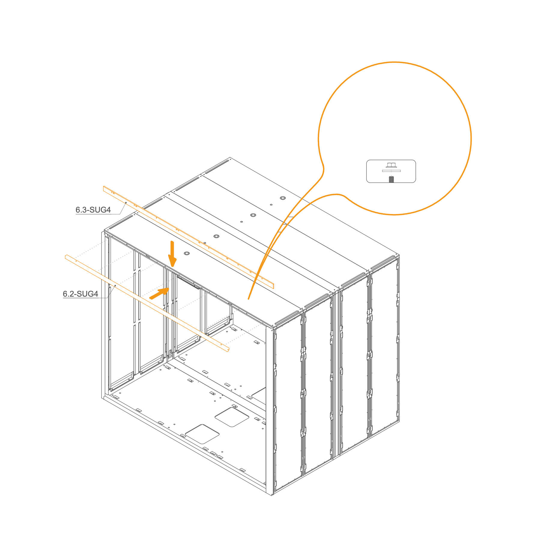
22. Attach Rear Frame to the Roof
- Identify parts 6.2-SUG4 and 6.3-SUG4.
- Place the frame at the top of the rear frame, aligning them with the corresponding holes.
- Secure the profile using M6 flange nuts (T0514) and washers (T0198) as indicated.
Parts used:
-
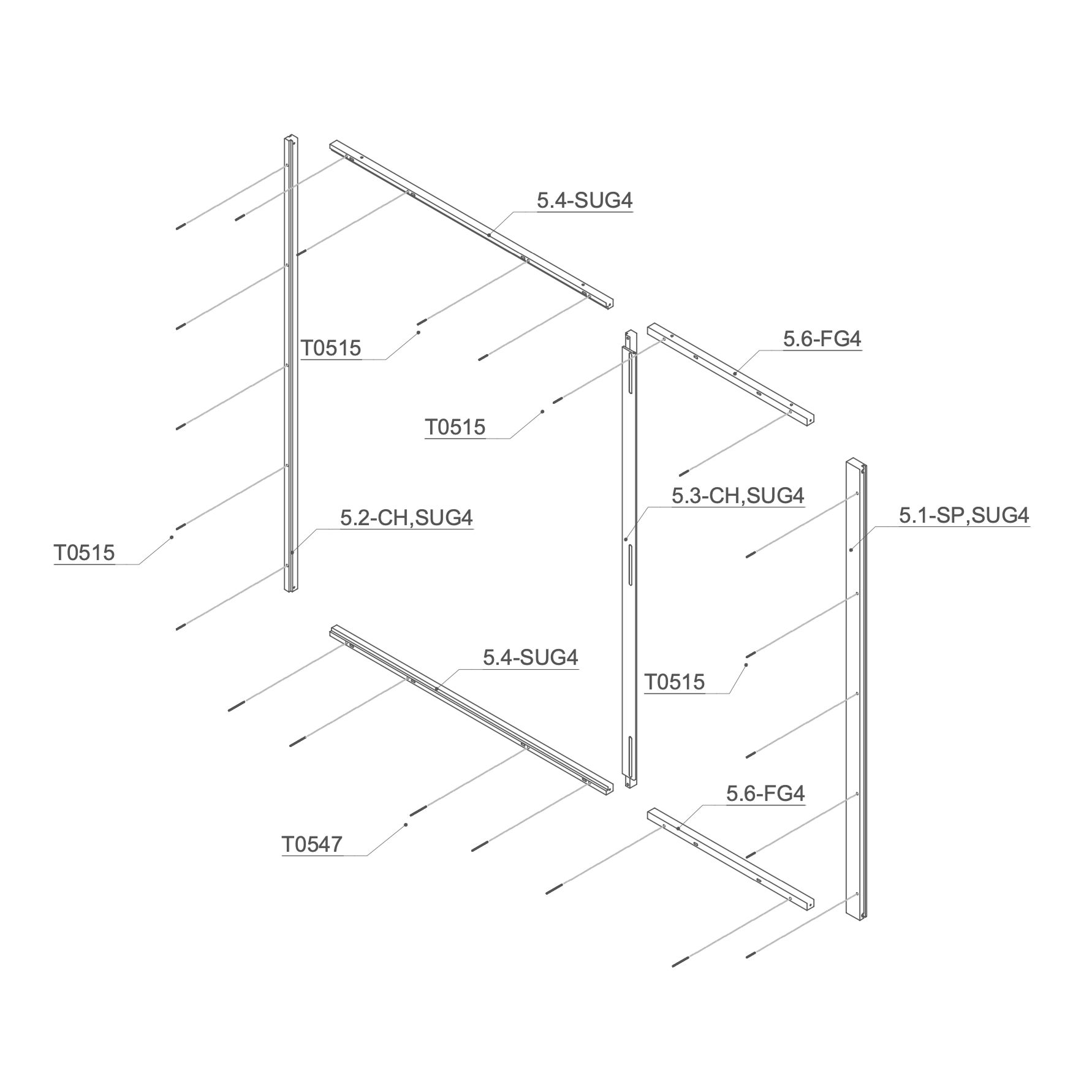
Front Frame 23. Attach the Threaded Rod to Front Frame
-
Place the M6×90 mm threaded rod (T0547) into one 5.4-SUG4 and one 5.6-FG4 Frame.
-
Insert M6×50 mm threaded rod (T0515) into the 5.2-CH,SUG4, 5.3-CH,SUG4, 5.4-SUG4 and 5.6-FG4 Frame.
Parts used:
-
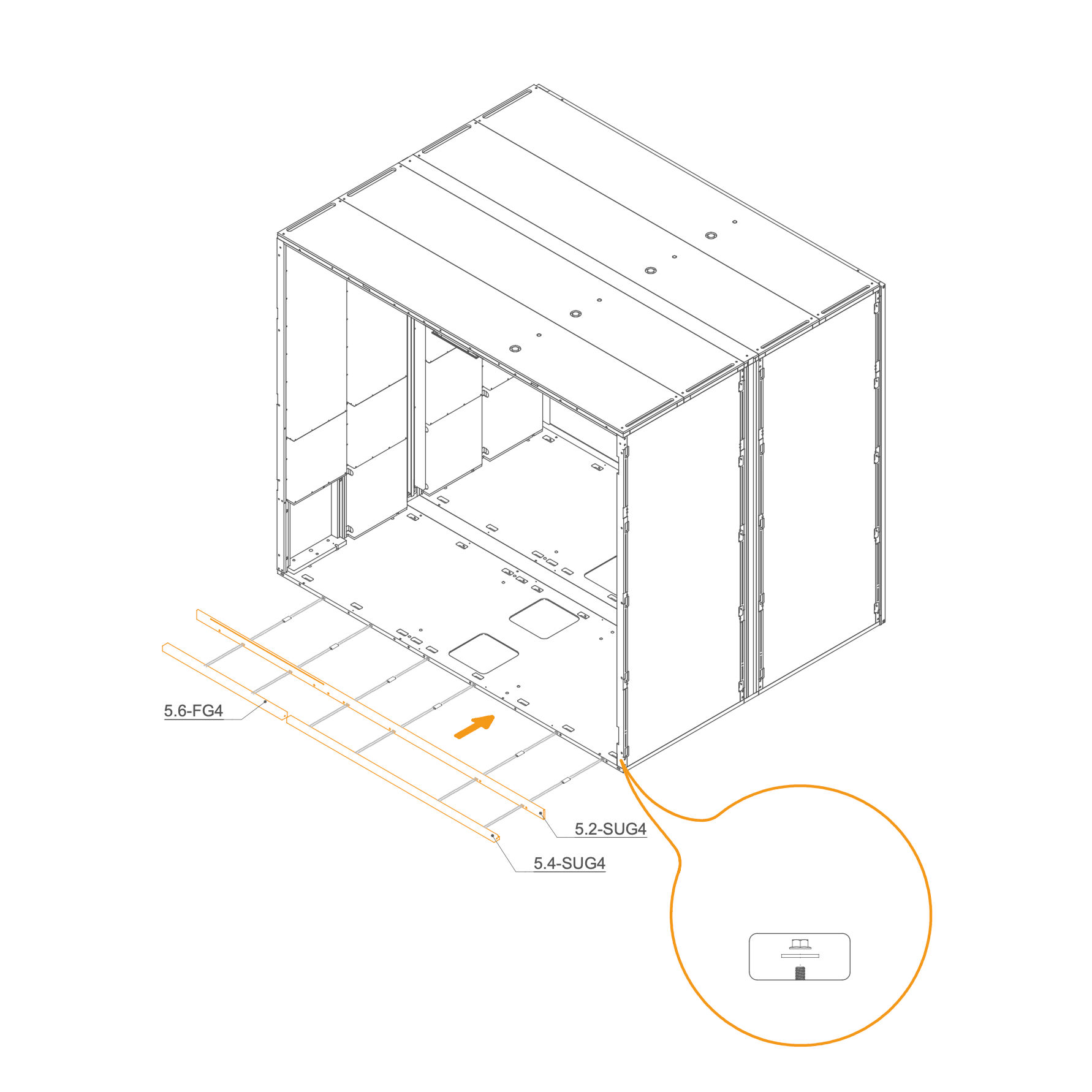
24. Attach Front Frame to the Floor Panel
-
Insert D8×50×22 mm dowels (T0536) into the oval holes.
-
Align the horizontal frame 5.4-SUG4 , 5.6-FG4 and 5.2-SUG4 with the mounting slots at the rear edge of the floor panel.
-
Place washers (T0198) and M6 flange nuts (T0514) on the threaded rod in the floor cutouts.
-
Ensure the frame is aligned correctly before tightening properly.
Parts used:
-
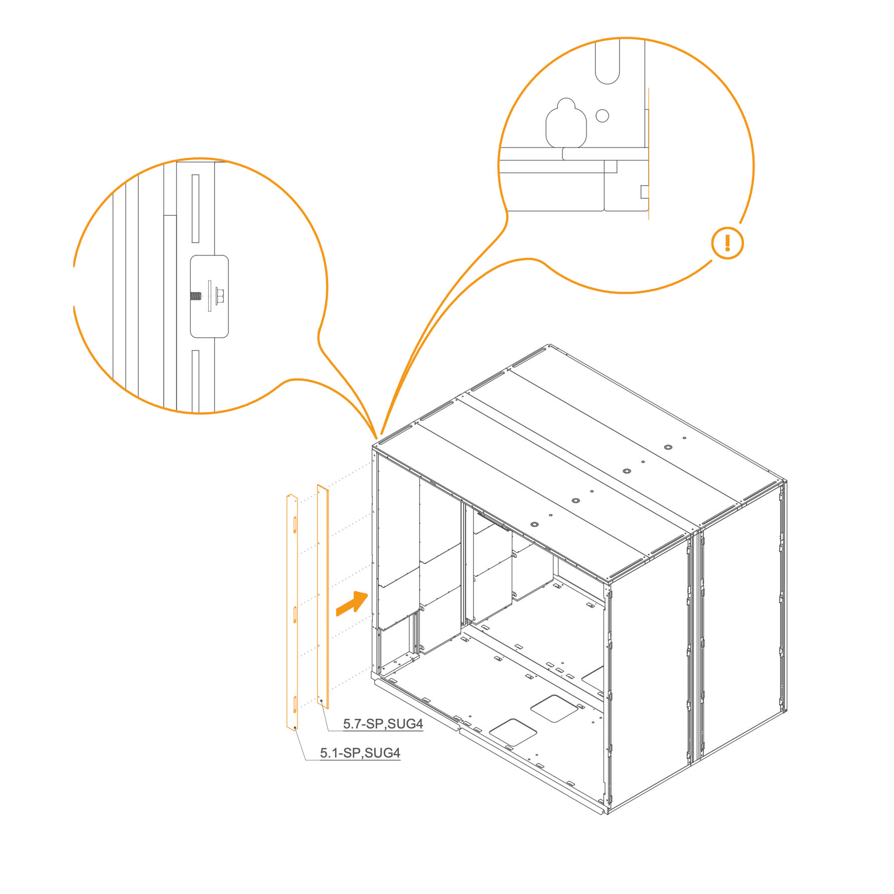
25. Attach Front Frame to the Dock
-
Place the two vertical frames, 5.1-SP,SUG4 and 5.7-SP,SUG4, in their designated positions.
-
Secure each frame by inserting a washer (T0198) and tightening an M6 flange nut (T0514) onto the threaded rod in the slot openings.
-
Ensure the frames are properly aligned before fully tightening the nuts.
Parts used:
-
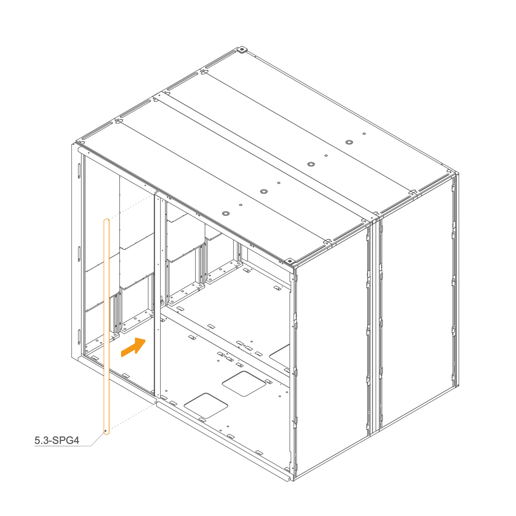
26. Attach Door Front Frame
-
Position panel 5.3-SPG4 vertically in the center front section of the frame.
-
Align it carefully with the mounting points.
-
Secure using M6 flange nuts (T0514) and washers (T0198).
Parts used:
-
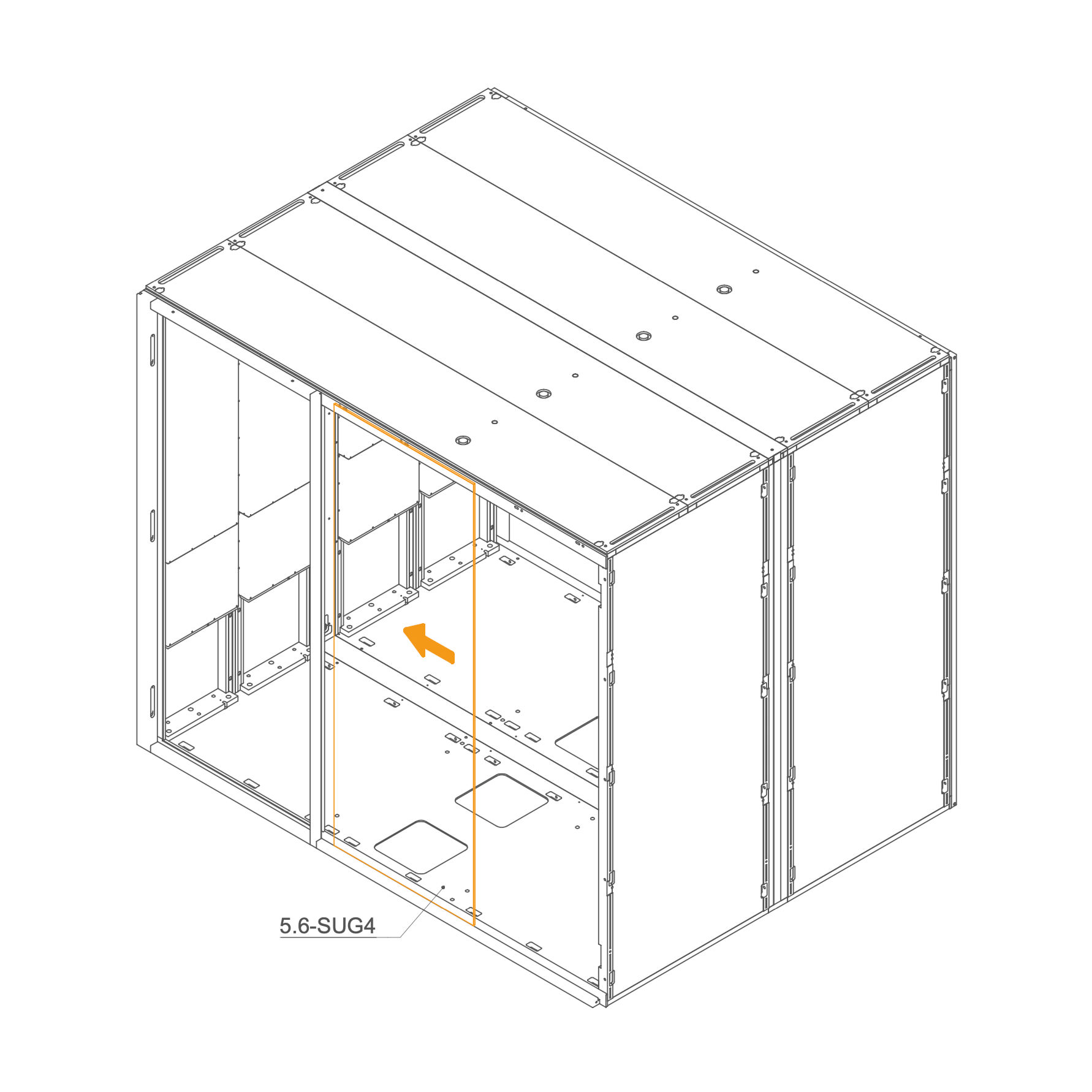
27. Install Front Glass into the Frame
-
Clean the edge of the glass with the glass cleaner to remove any dust or grease.
-
Carefully apply double-sided gel tape along the cleaned edge. Do not remove the protective foil from the tape at this stage.
-
Insert the glasses (5.6-SUG4) into the groove in the Rear frame.
-
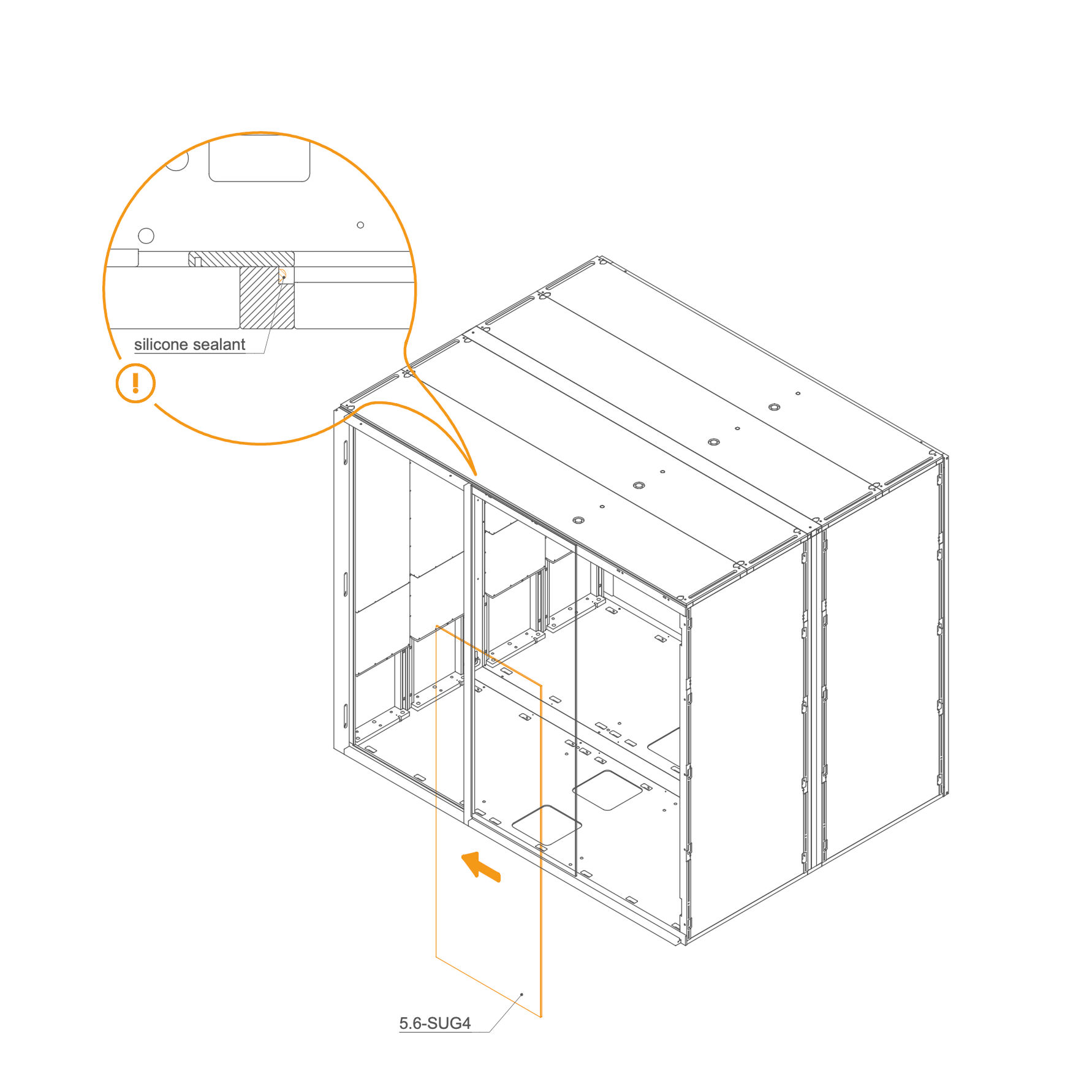
28. Install glass panel on front frame
- Apply silicone sealant into the groove in the frame.
- Insert the glass panel 5.6-SUG4 into position, aligning it with the groove.
- Press the panel carefully into place to ensure a firm bond.
-
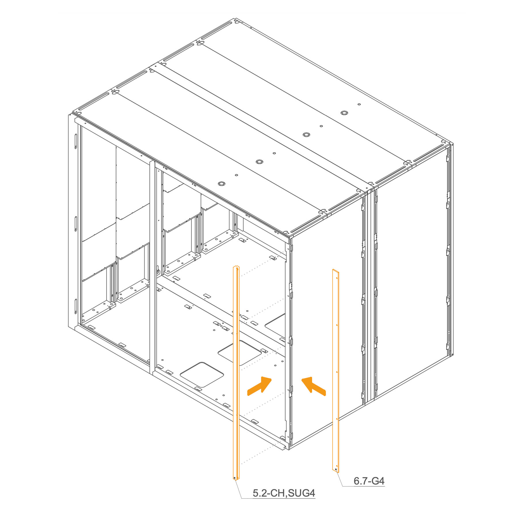
29. Attach Rear Frame to the Dock
- Locate part 5.2-CH,SUG4 (front right vertical profile) and 6.7-G4 (front left vertical profile).
- Align each profile with the corresponding front frame posts.
- Secure Rear frame using M6 flange nuts (T0514) and washers (T0198).
Parts used:
-
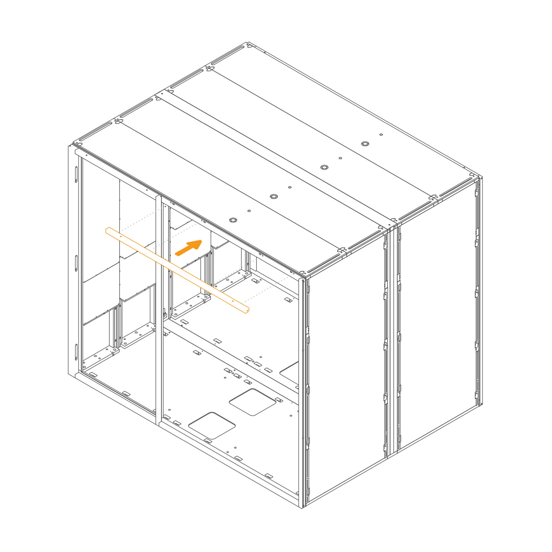
30. Attach Front Frame to the Roof
- Insert horizontal frame 5.4-SUG4 , in their designated positions.
- Secure each frame by inserting a washer (T0198) and tightening an M6 flange nut (T0514) onto the threaded rod in the slot openings.
- Ensure the frames are properly aligned before fully tightening the nuts.
Parts used:
-
31. Secure the Rear frame and the Front frame
- Insert M4×45 mm bolts through the frame as shown to fasten the structure.
Parts used:
- M4×45 mm bolt | T0535 | 8×
-
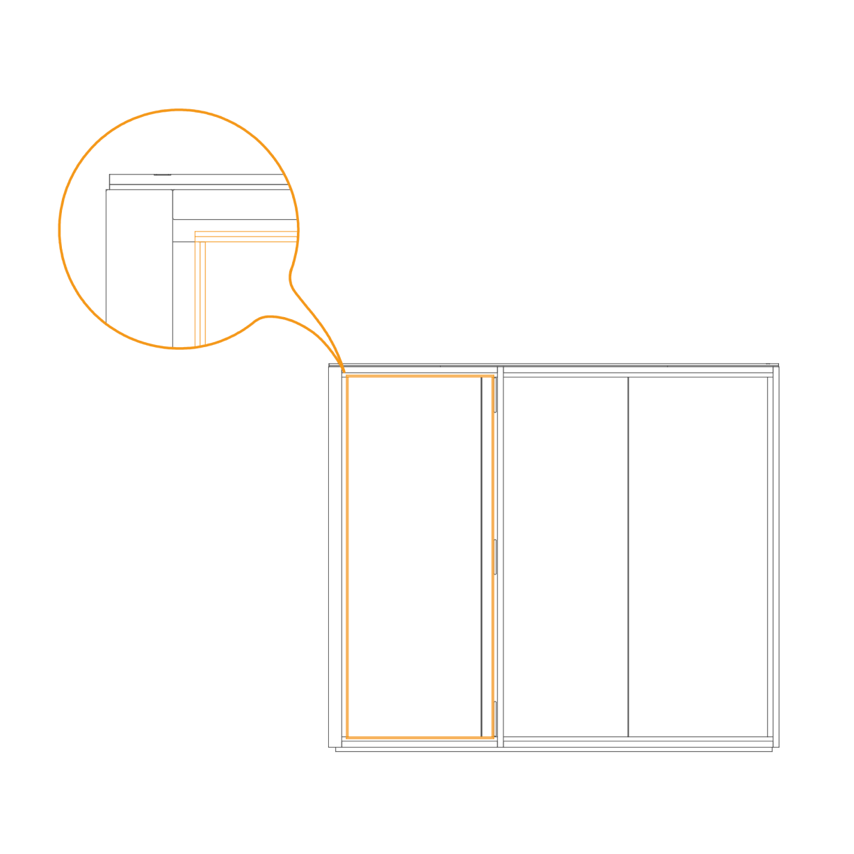
32. Install the door seal
- Position the vertical seal along the edge of the door frame as shown.
- Press the seal firmly into place to ensure a continuous, tight fit from top to bottom.
-
Door 33. Attach door cross brace to panel
- Place the glass 5.11-F,CH,SUG4 on the working stand.
- Insert the plastic insert (O0433) into the countersunk holes in the glass, and secure the frame to the glass using M8×25 mm screws (T0512).
Parts used:
-
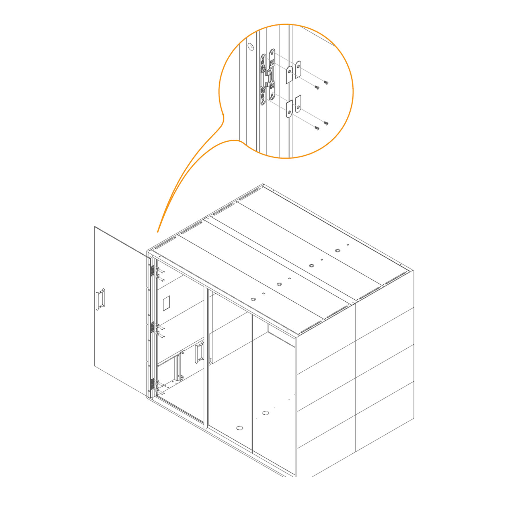
34. Attach hinges
- Attach hinges (V0002) into the recess use M4×30 mm screws to secure the position.
- Repeat for all 3 positions as shown.
Parts used:
-
35. Secure the Door in the Frame
- Place the door into the recesses in the frame and secure it with screws M4×30 mm (T0070).
Parts used:
- M4×30 mm screw | T0070 | 6×
-
36. Install door reinforcement bracket
- Align the two parts of the handle on either side of the hole in the glass.
- Insert the enclosed M6×120 mm screw through the hole and fasten the handle parts using a 4 mm hex key.
- Place the plastic spacer between the screw and the glass to prevent direct contact.
- Tighten the screw securely, ensuring the handle is firmly attached without over-tightening.
Parts used:
-
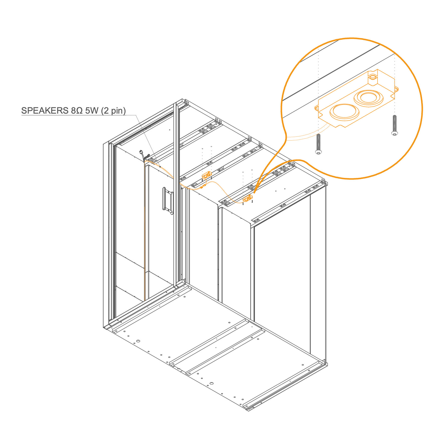
Light 37. Install ceiling speakers
- Position the speaker modules in the predrilled ceiling holes.
- Secure each speaker with two M4x10 screws (T0499).
- Plug the corresponding cable SPEAKERS 8Ω 5W (2 pin) to the speakers.
Parts used:
-
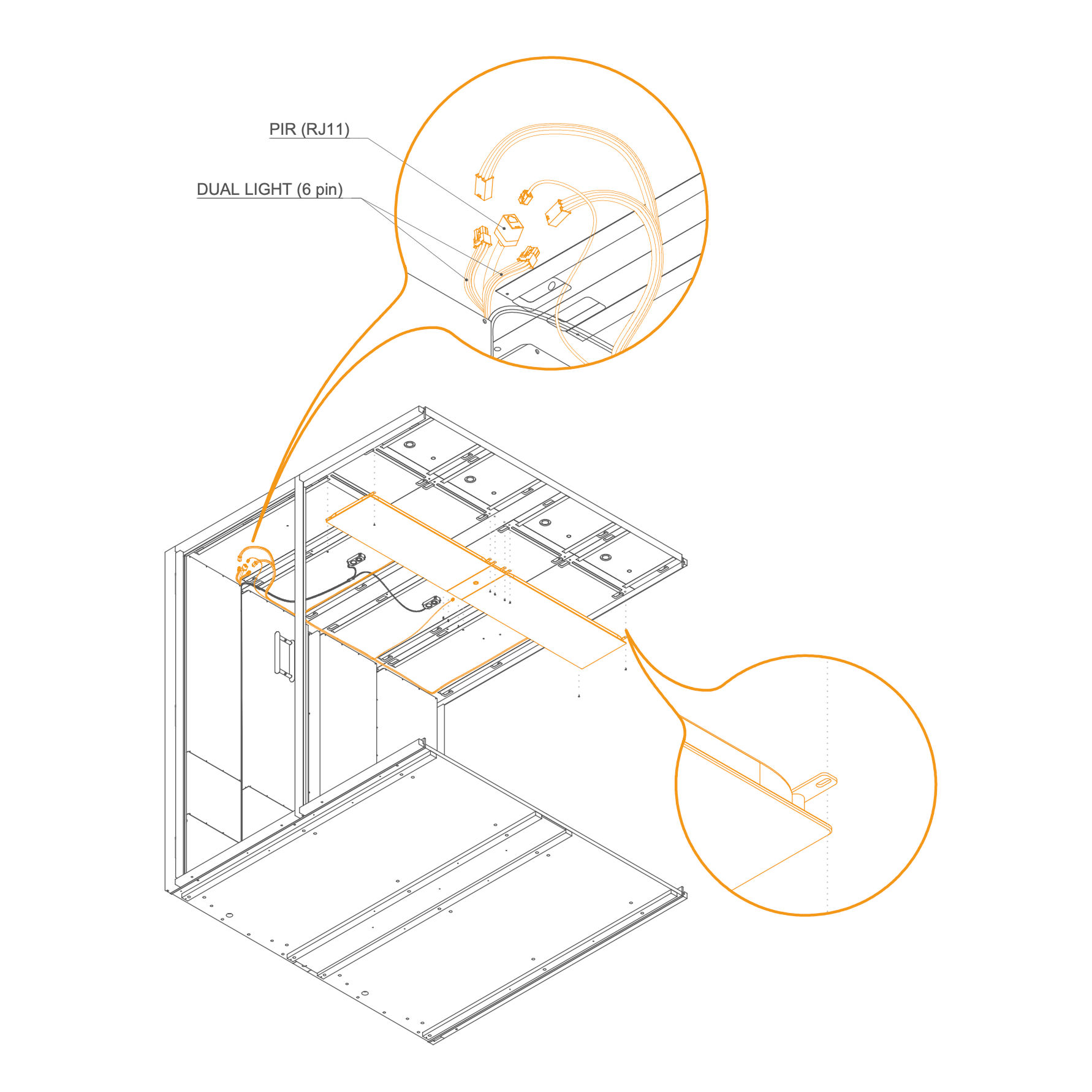
38. Connect sensor and light cables
- Connect the PIR sensor cable (RJ11) and the dual light cable (6 pin).
- Position and secure the light panel to the ceiling using screws.
Parts used:
-
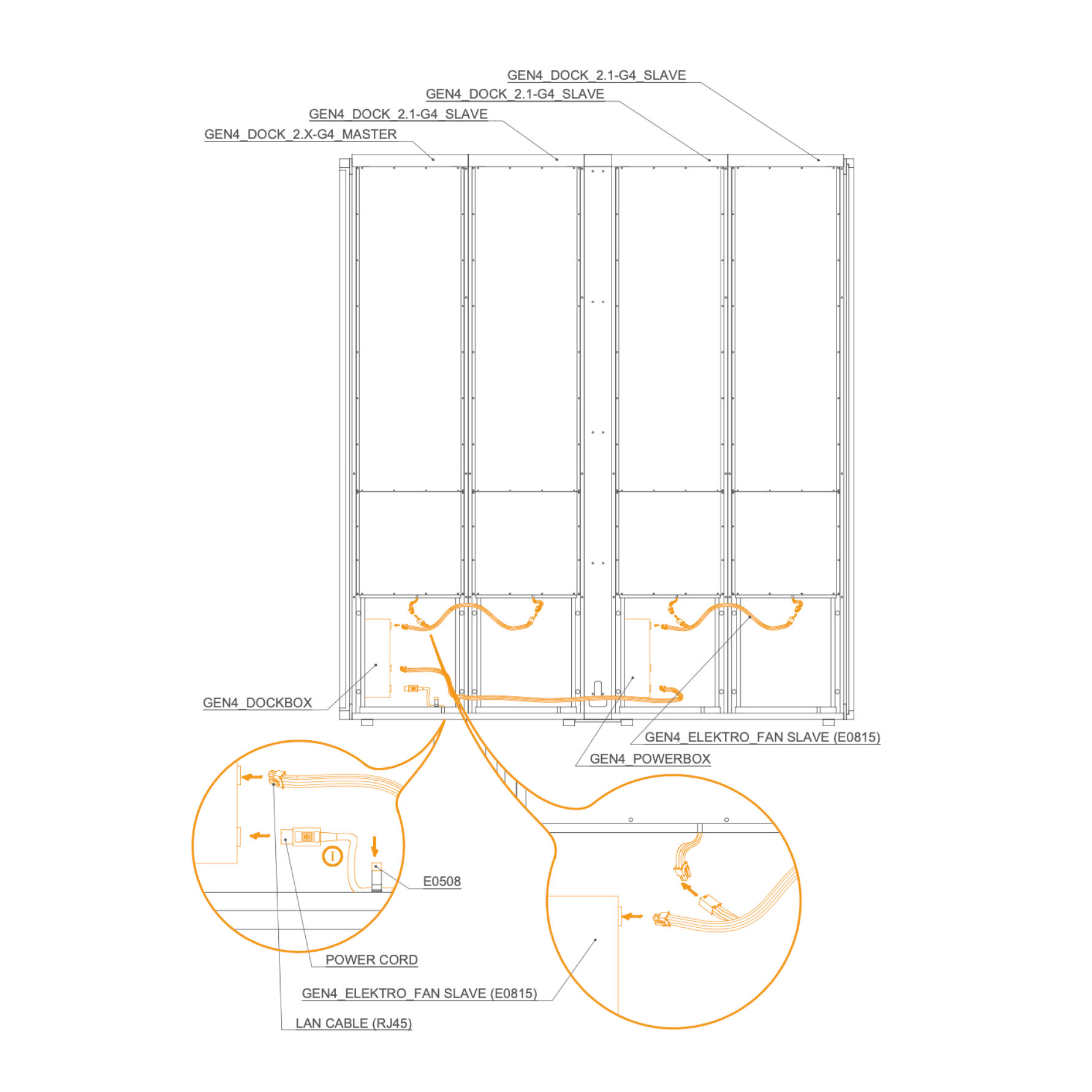
Electro Connection 39. Electro connection
-
Connect GEN4_DOCK_2.X-G4_MASTER to GEN4_DOCK_2.1-G4_SLAVE units.
-
Connect each GEN4_DOCKBOX to the corresponding GEN4_ELEKTRO_FAN SLAVE (E0815).
-
Connect the LAN cable (RJ45) and the power cord to the GEN4_POWERBOX.
-
After testing the connection, unplug the power cord.
-
External Panels 40. Attach Eternal Panels
- Install the upper panels 8.3-SUG4 by aligning them with the edge of the frame and the screw holes.
- Prepare the lower panels 8.2-SUG4 by positioning them underneath the frame. You may use spacers or supports to make fastening easier.
Parts used:
-
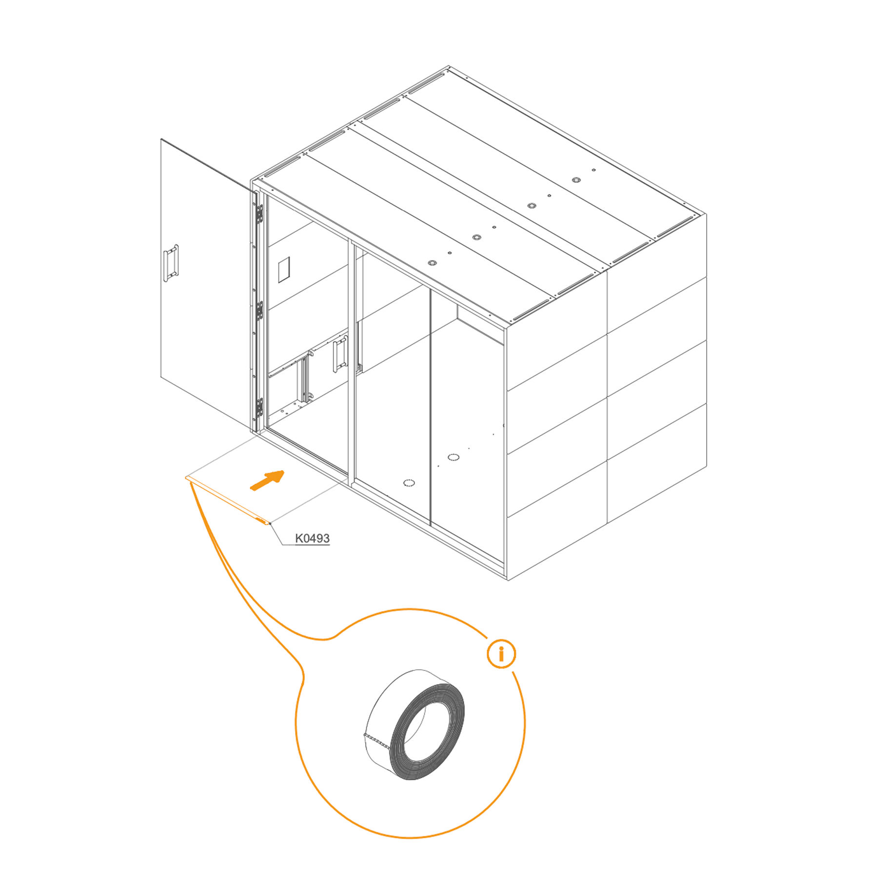
41. . Fix the External Panels
- Secure the previously placed external panels using M6×40 mm screws (T0397).
Parts used:
-
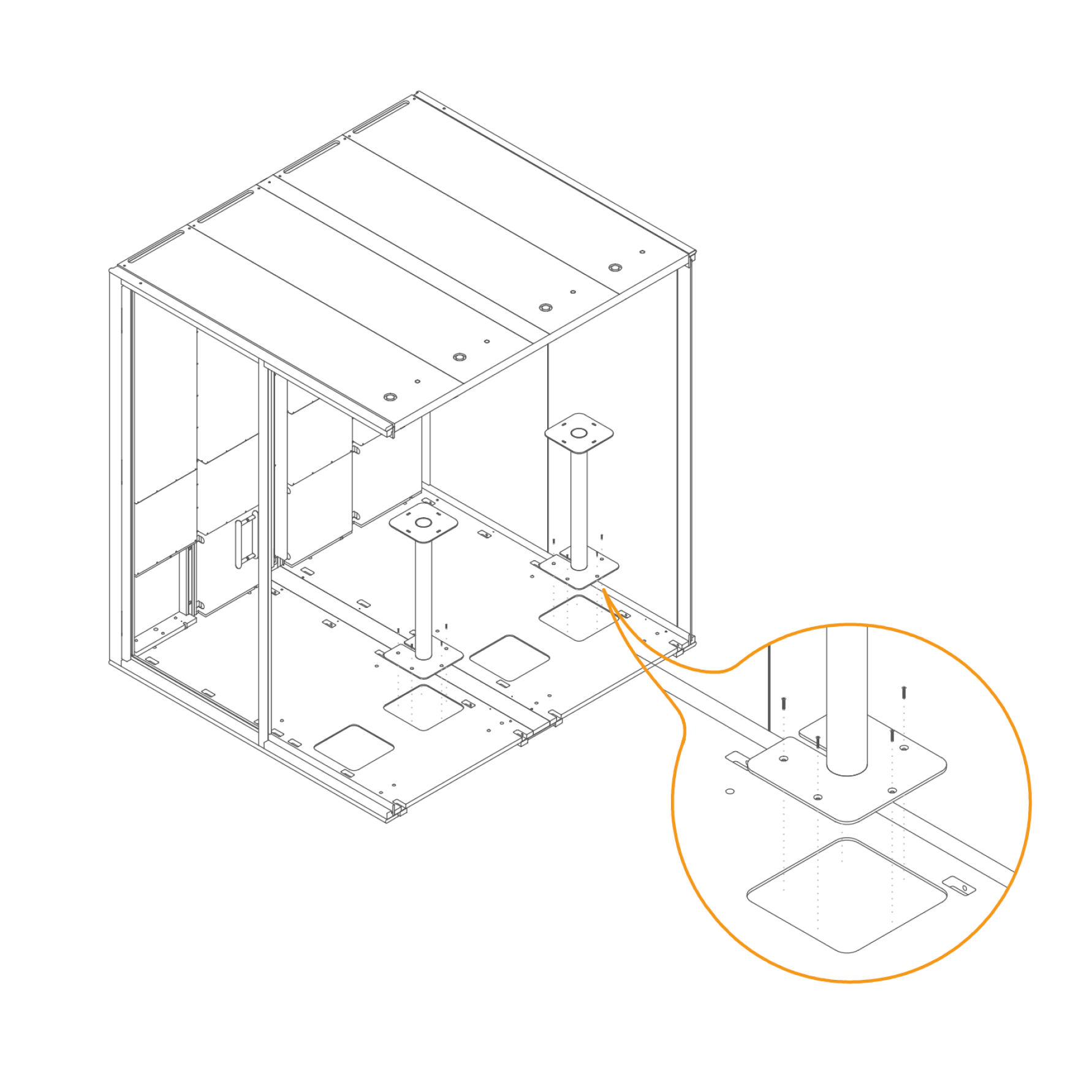
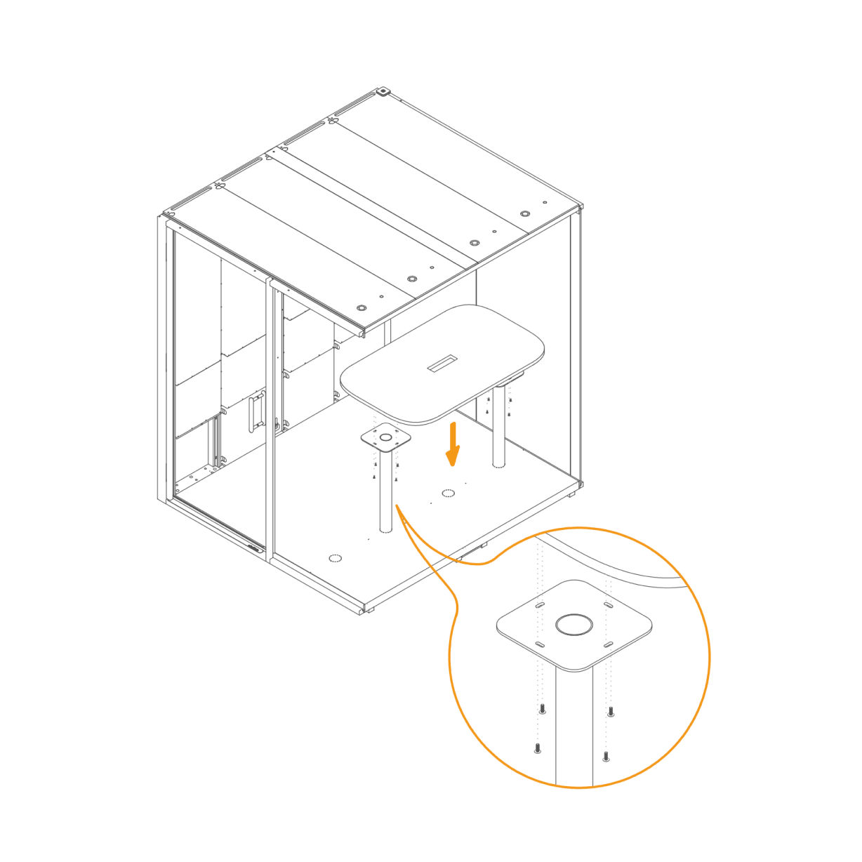
Table 42. Attach Table Supports to the Floor -
43. Place Floor Covers -
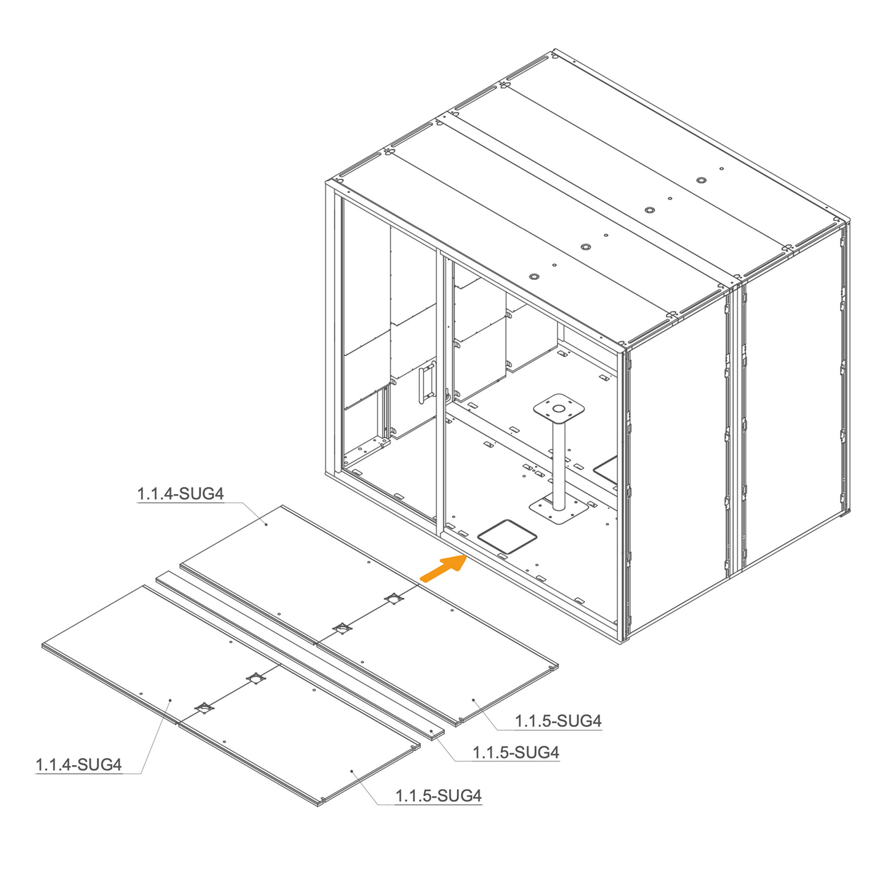
Floor Isolation, Carpet and Table 44. Place Floor Isolation Panels inside the Pod
-
Place the floor insulation panels inside the pod as shown.
-
Ensure correct placement: panels marked 1.1.4-SUG4 go on the left side, and 1.1.5-SUG4 panels cover the right and 9.1.2-SUG4 on the center section.
Parts used:
-
Floor insulation | 1.1.4-SUG4 | 2×
-
Floor insulation | 1.1.5-SUG4 | 2×
-
Floor insulation | 9.1.2-SUG4 | 1×
-
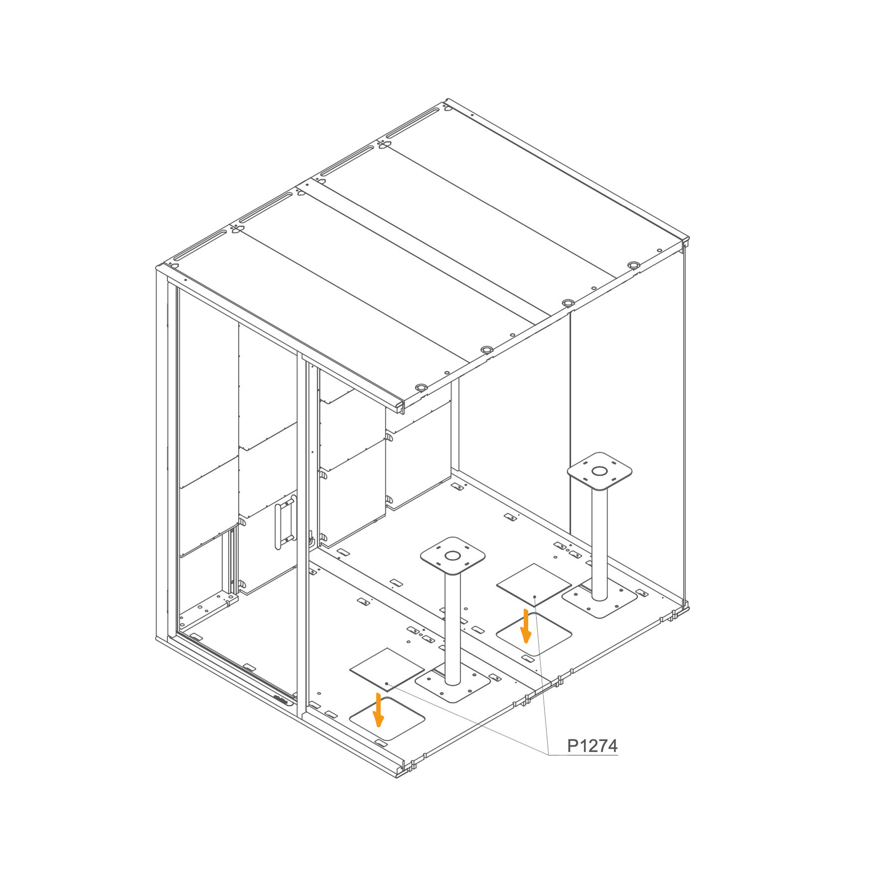
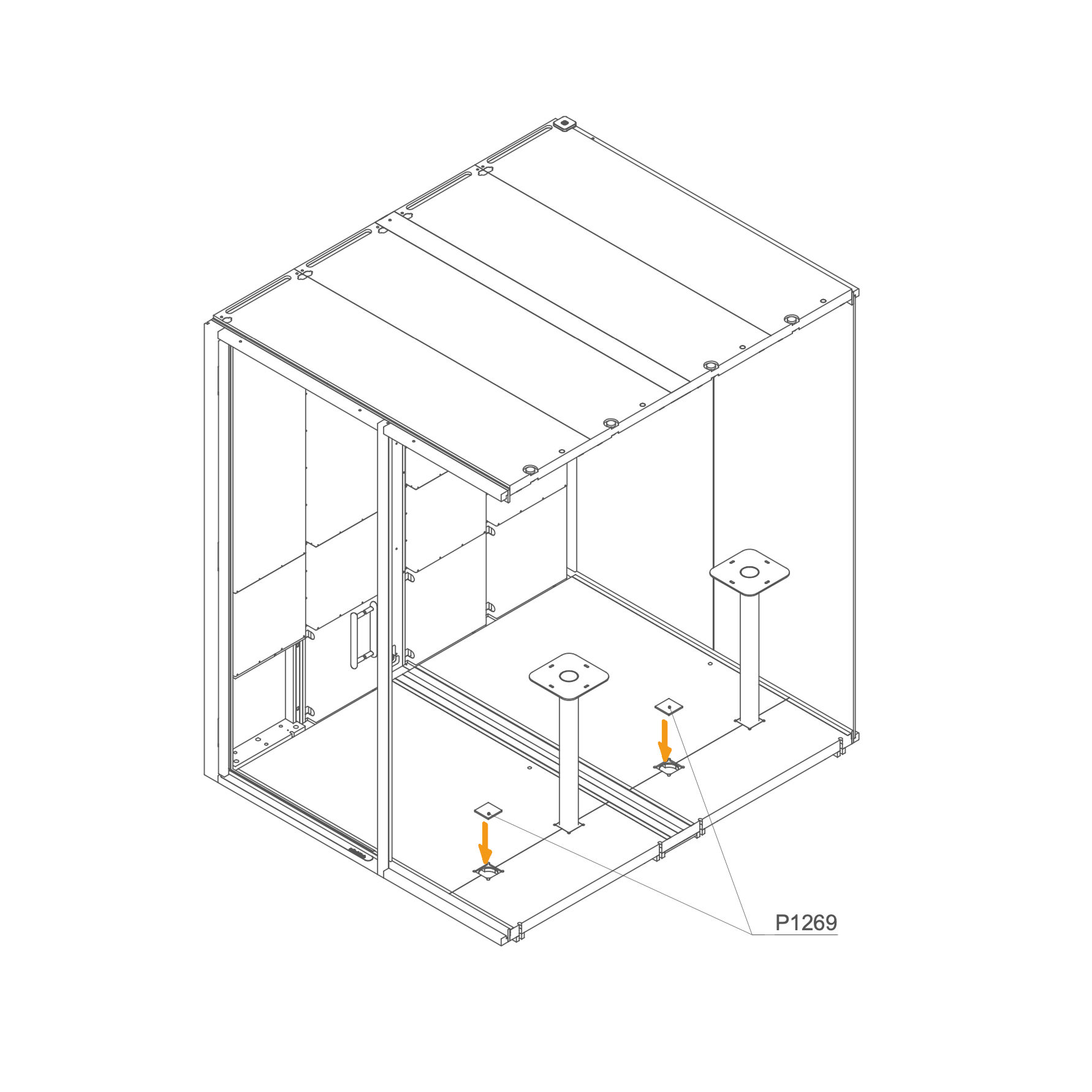
45. Insert Blind Plug into the Opening
- Insert the insulation blind plug P1269 into the corresponding openings.
Parts used:
-
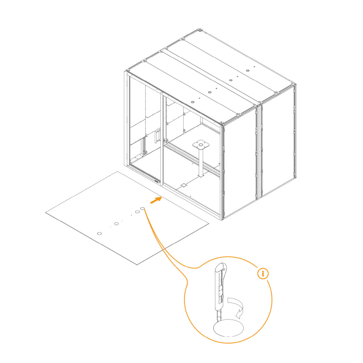
46. Lay Carpet on the Floor
- Place the carpet into position.
- If a table is being installed, use a utility knife to cut openings in the carpet for the table legs.
- The position of these openings is indicated by perforations on the carpet.
Parts used:
-
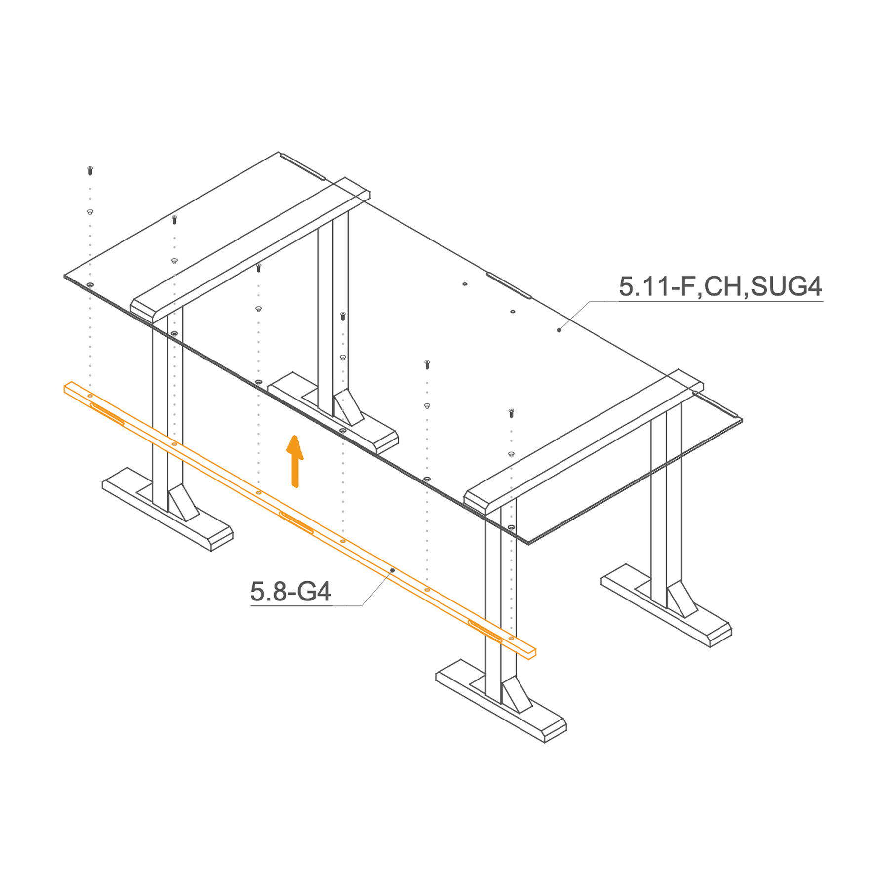
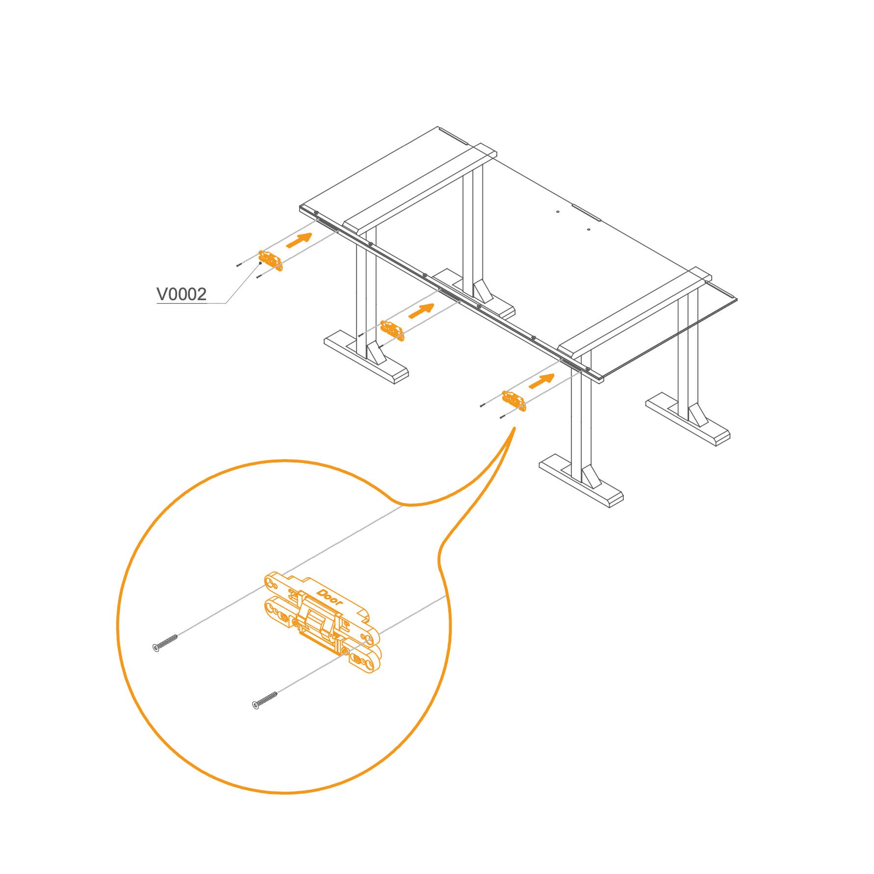
47. Attach Tabletop to the Table Leg
- Place the tabletop onto the table leg.
- Align the holes underneath the tabletop with the mounting holes on the leg.
- Fasten using the provided screws.
Parts used:
- M6×16 mm flat head bolt | T0322 | 8×
-
Occupancy Light Cable 48. Route the Occupancy Light Cable through the Frame
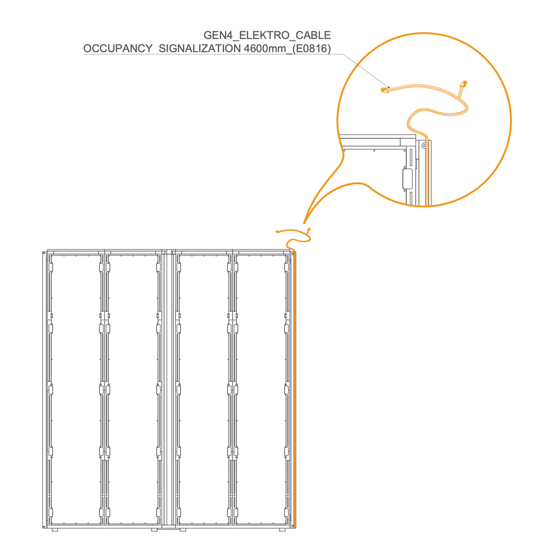
- Route the GEN4_ELEKTRO_CABLE OCCUPANCY SIGNALIZATION 4600 mm (E0816) in the groove as shown.
-
Interior Panels 49. Insert Display into the Interior Panel
-
Place the display into the interior panel cutout from the front.
-
Route the cables through the cutout.
-
Secure display from behind using the plastic cover and screws.
-
50. Install Interior Panels
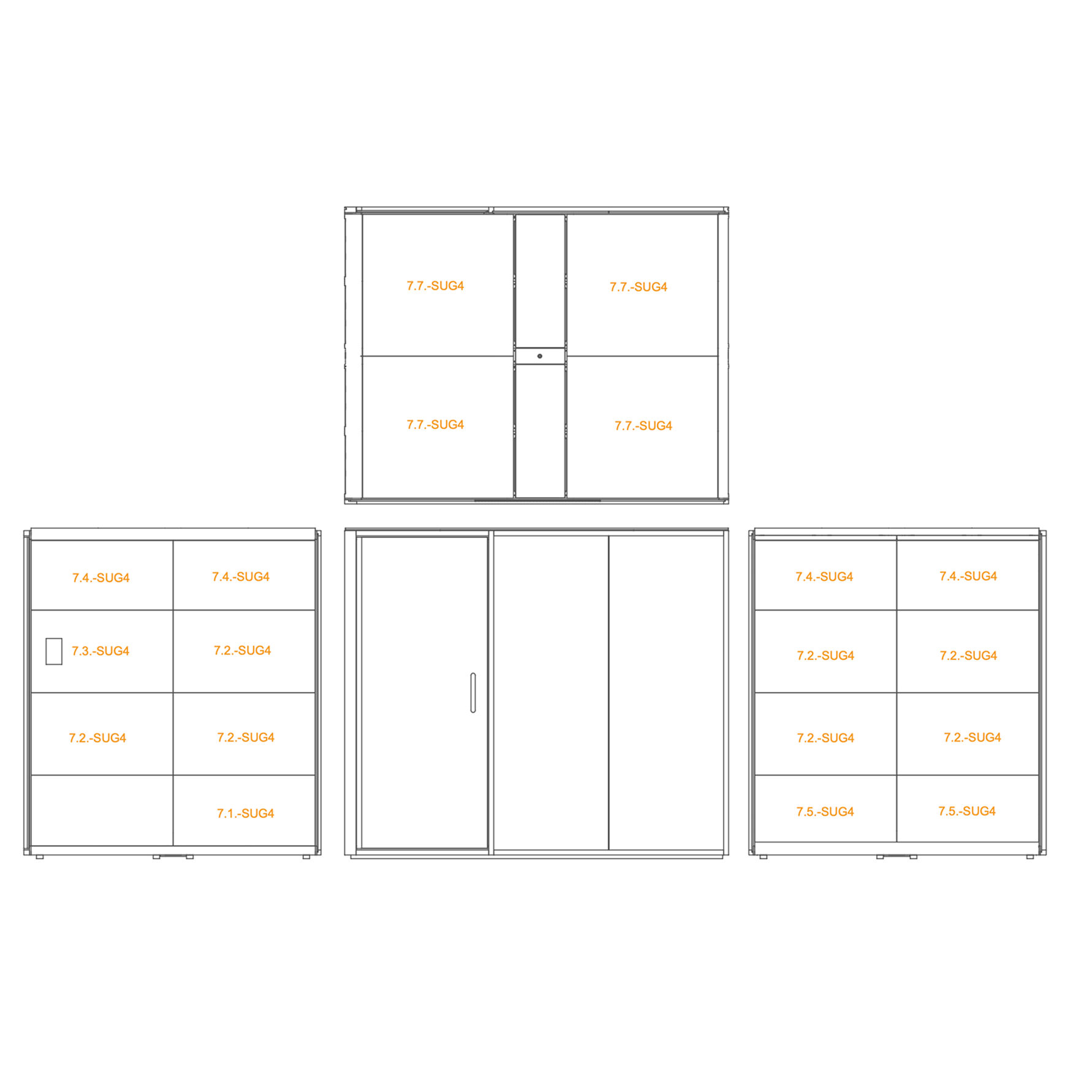
- Position the labeled interior panels (as per the diagram) in their designated locations inside the accoustic pod.
-
Exterior Panels 51. Install External panels
-
Insert pins into the pre‑drilled holes of the bottommost panels.
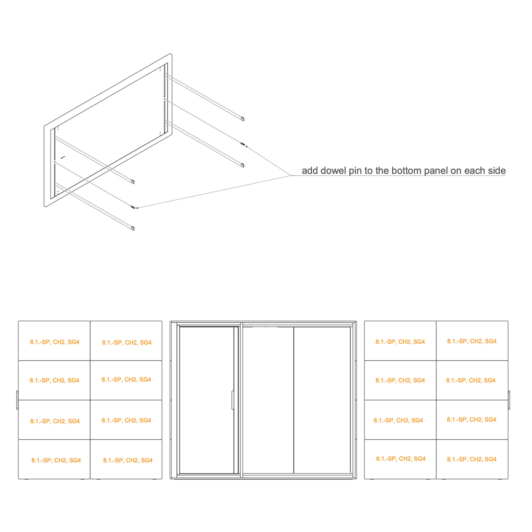
-
Install a minimum of four clip connectors into the external panel.
-
Fit the adjacent panels as shown in the illustration. Begin installation from the bottom and move upward sequentially.
Parts used:
-
external panel | 8.1-SP, CH2, SG4 | 16×
-
clip connector | T0122 | 64×
-
8×30 mm dowel pin | T0122 | 4x
-
Occupancy Lights 52. Install occupancy light
-
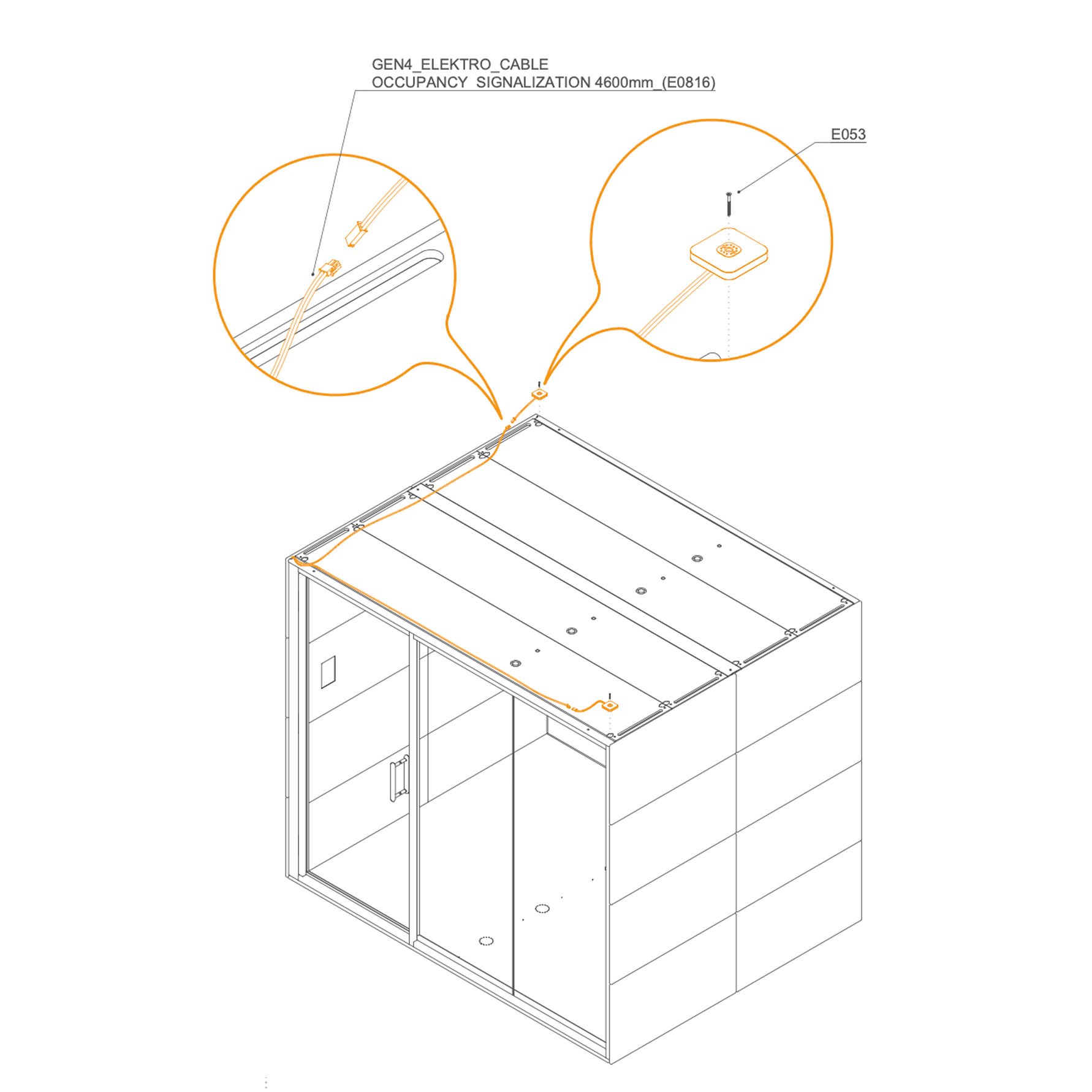
Route the GEN4_ELEKTRO_CABLE OCCUPANCY SIGNALIZATION 4600 mm (E0816) as shown.
-
Connect the cable to the occupancy light.
-
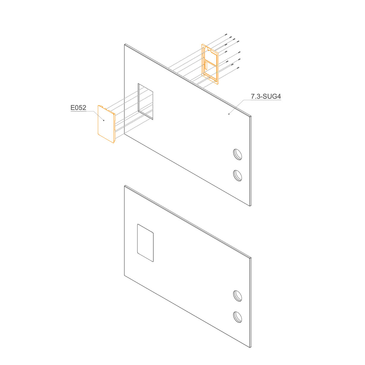
Secure the occupancy light (E053) to the frame with the provided screws.
Parts used:
- occupancy light | E053 | 2×
- 3×30 mm screw | T0136 | 2×
-
Door Ajustment 53. Adjust the door Check the door adjustment in the video. -
Hinge Cover 54. Install Hinge Cover
Parts used:
- hinge cover | not labeled | 6×
- M4×10 mm screw | T0310 | 12×
-
Ledge 55. Install Ledge
Parts used:
- double-sided tape | B0007 | 1x
-
56. Install Ledge -
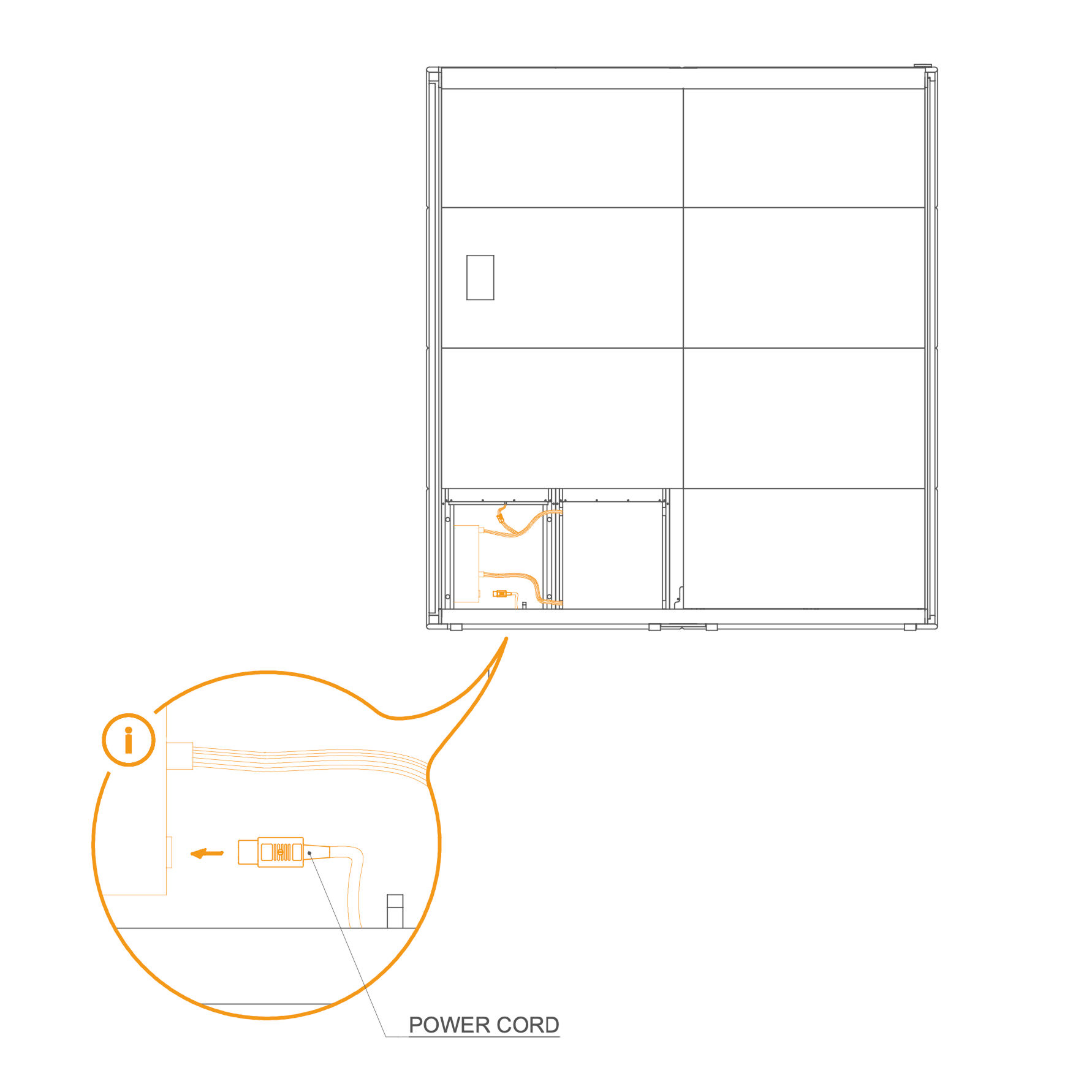
Cord Connection 57. Connect the Power Supply Cord to Powerbox -
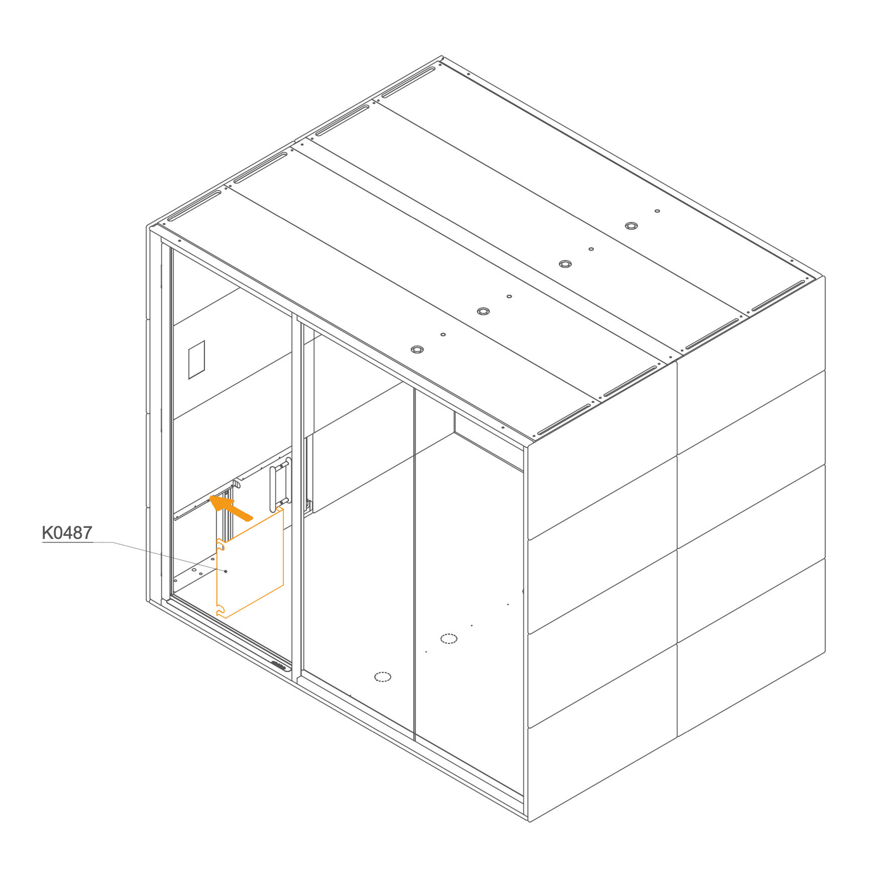
58. Install the Revision Door
- Position the cover (K0487) over the power cord and secure it in place.
Parts used:
-
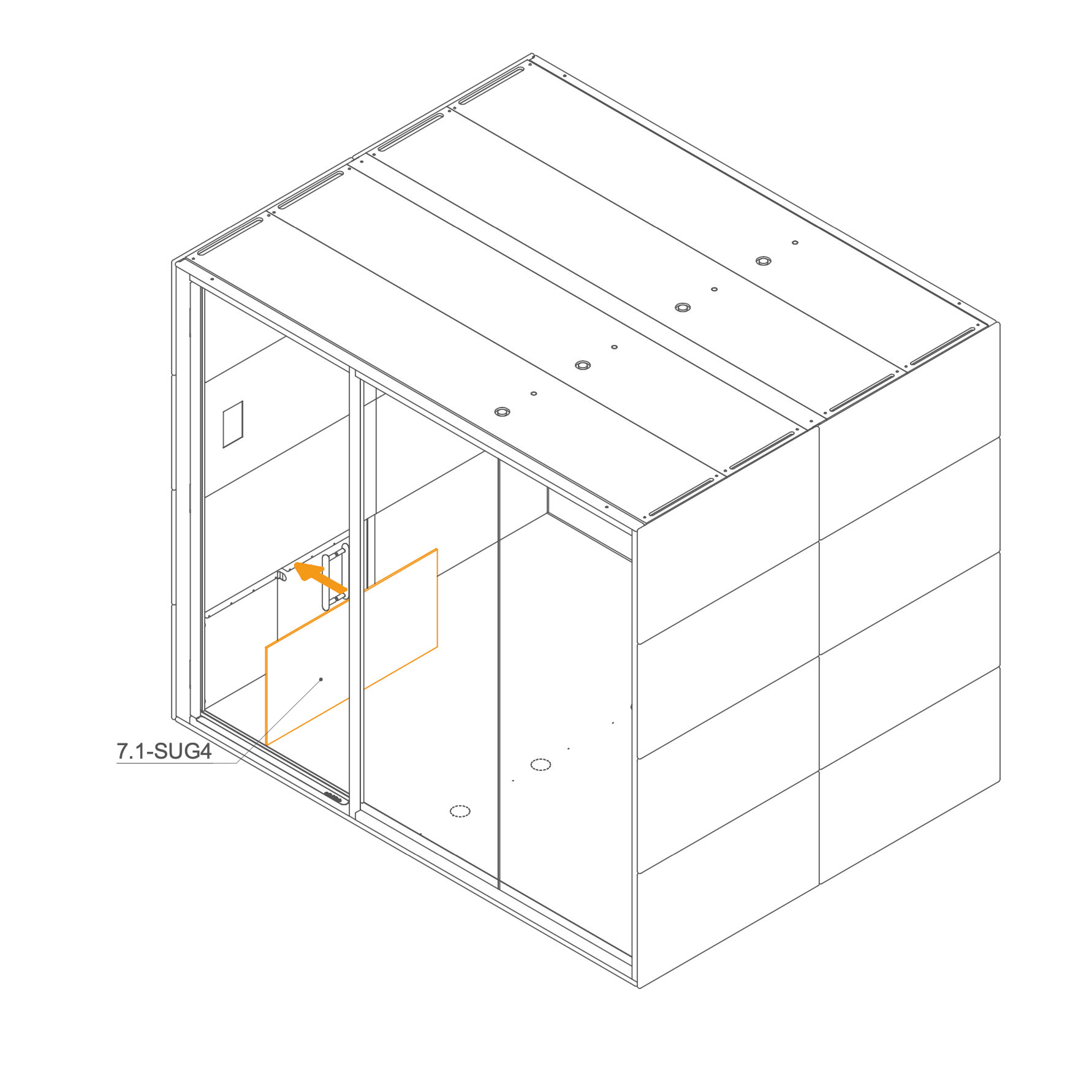
59. Install the internal panel cover
- Place the internal panel 7.1-SUG4 over the power cord section and secure in position.
Parts used:
- Internal panel | 7.1-SUG4 | 1×
-
Initial Setup 60. Initial Setup Following assembly, authorized personnel must perform a mandatory initial setup for all GEN4 products. This involves accessing the display settings to configure key parameters, such as the pod model, language, and time synchronization, to ensure all components function correctly.
Refer to Configuration Guide.
-
Final Checklist 61. Final checklist
-
Clean the glass with paper towels.
-
Adjust the door when needed.
-
Check the functionality of the sockets.
-
Check the functionality of the control panel.
After the Microoffice is assembled, please fill out the checklist.
|